à son minimum. C'est à notre avis la direction la plus intéressante pour poursuivre ...... the timeout delay ∆to: the time between the last reception of an “I am.
THÈSE DE DOCTORAT DE L’UNIVERSITÉ DU HAVRE
Spécialité INFORMATIQUE
Présentée par Olivier MARIN
Sujet de la thèse
The DARX Framework: Adapting Fault Tolerance For Agent Systems
Soutenue le 3 décembre 2003, devant le jury composé de :
Alain Cardon, Professeur à l’Universite du Havre
Directeur
André Schiper, Professeur à l’EPFL Maarten van Steen, Professeur à la Vrije Universiteit
Rapporteur Rapporteur
Jean-Pierre Briot, Professeur au LIP6 Marc-Olivier Killijian, Chargé de Recherches au CNRS à Toulouse Benno Overeinder, Maître de Conférences à la Vrije Universiteit Pierre Sens, Professeur à l’Université Paris VI
Examinateur Examinateur Examinateur Examinateur
To my late father, Hope this would have made you proud.
Thanks
Firstly I wish to thank thoroughly Professor Alain Cardon, from Le Havre University, Director of the Laboratoire d’Informatique du Havre (LIH), for providing a true frame for this thesis. Quite simply his cleverness in advice, his sympathy, and his generosity made this work possible; more importantly those same qualities made it enjoyable. Eternal thanks to Professor Pierre Sens, from Paris VI University, for being a one in a million advisor, for creating the perfect alchemy between guidance and independence, for being both a reliable, humane support and an impressive professional example. I wish to address cordial thanks to Professor André Schiper, from the École Polytechnique Fédérale de Lausanne, and to Professor Maarten van Steen, from Vrije Universiteit van Amsterdam, for the interest they’ve shown for my work and for accepting to review this thesis. Many thanks go to Professor Jean-Pierre Briot, from Paris VI University, and Doctor Benno Overeinder, from Vrije Universiteit van Amsterdam, for both their numerous contributions to my work and their extremely friendly approach to research cooperation. Many thanks to them and also to Doctor Marc-Olivier Killijian for accepting to take part in my jury. Very special thanks to Marin Bertier, Zahia Guessoum, Kamal Thini, Julien Baconat, Jean-Michel Busca and the other members of the ARP (Agents Résistants aux Pannes) team; their participation to the DARX project is invaluable. Most of the work presented in this thesis would not have been possible without them. Grateful thanks to the members of the SRC (Systèmes Répartis et Coopératifs) team at the LIP6 (Laboratoire d’Informatique de Paris 6); together they create a fantastic ambiance, providing a most friendly and motivating environment to work in. I cannot stress how much I appreciated spending those three years among them. The same goes to the members of the LIH, whom I will fondly remember as great colleagues as well. Great thanks to the IIDS (Intelligent Interactive Distributed Systems) group at the Vrije Universiteit, for having hosted me on several occasions and for the very fruitful cooperation that ensued.
I wish to express all my gratitude to my family and friends: to my mother who was there supporting every step, to my sister for her inspiring strong will, to Fatima for her tender and loving care, to Chloë, Hervé, Magali, Arthur, Gaëlle, Benoît, Ruth, Grég, Sabrina, Frédéric, Carole, Nimrod, Isa, Sophie and all the many others for their unconditional friendship. I thank you all for your kind, witty, and encouraging presence at all times. Thanks to Mme Florent, philosophy teacher at the Lycée Pasteur, and to a few others in the french educational system, for showing me the way to perseverance in the face of adversity. I would particularly like to thank Mr Saint-Blancat, german teacher at the CES Madame de Sévigné, and Dr Françoise Greffier, from the LIFC at Besançon University, for kindly choosing the smoother, humane option: trust and support.
Table of Contents 1 Introduction 1.1 Multi-agent systems
1 . . . . . . . . . . . . . . . . . . . . . . . . . . .
1
1.2 The reliability issue . . . . . . . . . . . . . . . . . . . . . . . . . . . .
3
1.3 Adaptive replication . . . . . . . . . . . . . . . . . . . . . . . . . . .
5
2 Agents & Fault Tolerance
7
2.1 Agent-based computing . . . . . . . . . . . . . . . . . . . . . . . . . .
9
2.1.1
Formal definitions of agency . . . . . . . . . . . . . . . . . . . 10
2.1.2
Multi-Agent Systems . . . . . . . . . . . . . . . . . . . . . . . 12
2.2 Fault tolerance . . . . . . . . . . . . . . . . . . . . . . . . . . . . . . 18 2.2.1
Failure models . . . . . . . . . . . . . . . . . . . . . . . . . . . 19
2.2.2
Failure detection . . . . . . . . . . . . . . . . . . . . . . . . . 20
2.2.3
Failure circumvention . . . . . . . . . . . . . . . . . . . . . . . 24
2.2.4
Group management . . . . . . . . . . . . . . . . . . . . . . . . 34
2.3 Fault Tolerant Systems . . . . . . . . . . . . . . . . . . . . . . . . . . 36 2.3.1
Reliable communications . . . . . . . . . . . . . . . . . . . . . 36
2.3.2
Object-based systems . . . . . . . . . . . . . . . . . . . . . . . 38
2.3.3
Fault-tolerant CORBA . . . . . . . . . . . . . . . . . . . . . . 40
2.3.4
Fault tolerance in the agent domain . . . . . . . . . . . . . . . 44
2.4 Conclusion . . . . . . . . . . . . . . . . . . . . . . . . . . . . . . . . . 47 3 The Architecture of the DARX Framework
49
3.1 System model and failure model . . . . . . . . . . . . . . . . . . . . . 52 i
ii
3.2
DARX components . . . . . . . . . . . . . . . . . . . . . . . . . . . . 55
3.3
Replication management . . . . . . . . . . . . . . . . . . . . . . . . . 58
3.4
3.5
3.6
3.3.1
Replication group . . . . . . . . . . . . . . . . . . . . . . . . . 58
3.3.2
Implementing the replication group . . . . . . . . . . . . . . . 62
Failure detection service . . . . . . . . . . . . . . . . . . . . . . . . . 66 3.4.1
Optimising the detection time . . . . . . . . . . . . . . . . . . 67
3.4.2
Adapting the quality of the detection . . . . . . . . . . . . . . 69
3.4.3
Adapting the detection to the needs of the application . . . . 73
3.4.4
Hierarchic organisation . . . . . . . . . . . . . . . . . . . . . . 74
3.4.5
DARX integration of the failure detectors . . . . . . . . . . . 76
Naming service . . . . . . . . . . . . . . . . . . . . . . . . . . . . . . 78 3.5.1
Failure recovery mechanism . . . . . . . . . . . . . . . . . . . 80
3.5.2
Contacting an agent . . . . . . . . . . . . . . . . . . . . . . . 81
3.5.3
Local naming cache . . . . . . . . . . . . . . . . . . . . . . . . 84
Observation service . . . . . . . . . . . . . . . . . . . . . . . . . . . . 88 3.6.1
Objective and specific issues . . . . . . . . . . . . . . . . . . . 88
3.6.2
Observation data . . . . . . . . . . . . . . . . . . . . . . . . . 91
3.6.3
SOS architecture . . . . . . . . . . . . . . . . . . . . . . . . . 94
3.7
Interfacing . . . . . . . . . . . . . . . . . . . . . . . . . . . . . . . . . 97
3.8
Conclusion . . . . . . . . . . . . . . . . . . . . . . . . . . . . . . . . . 99
4 Adaptive Fault Tolerance
101
4.1
Agent representation . . . . . . . . . . . . . . . . . . . . . . . . . . . 103
4.2
Replication policy enforcement . . . . . . . . . . . . . . . . . . . . . . 109
4.3
Replication policy assessment . . . . . . . . . . . . . . . . . . . . . . 112 4.3.1
Assessment triggering . . . . . . . . . . . . . . . . . . . . . . . 112
4.3.2
DOC calculation . . . . . . . . . . . . . . . . . . . . . . . . . 114
4.3.3
Criticity evaluation . . . . . . . . . . . . . . . . . . . . . . . . 116
4.3.4
Policy mapping . . . . . . . . . . . . . . . . . . . . . . . . . . 117
4.3.5
Subject placement . . . . . . . . . . . . . . . . . . . . . . . . 118
iii
4.3.6
Update frequency . . . . . . . . . . . . . . . . . . . . . . . . . 121
4.3.7
Ruler election . . . . . . . . . . . . . . . . . . . . . . . . . . . 122
4.4 Failure recovery . . . . . . . . . . . . . . . . . . . . . . . . . . . . . . 125 4.4.1
Failure notification and policy reassessment
. . . . . . . . . . 125
4.4.2
Ruler reelection . . . . . . . . . . . . . . . . . . . . . . . . . . 126
4.4.3
Message logging . . . . . . . . . . . . . . . . . . . . . . . . . . 127
4.4.4
Resistance to network partitioning . . . . . . . . . . . . . . . 130
4.5 Conclusion . . . . . . . . . . . . . . . . . . . . . . . . . . . . . . . . . 132 5 DARX performance evaluations
133
5.1 Failure detection service . . . . . . . . . . . . . . . . . . . . . . . . . 135 5.1.1
Failure detectors comparison . . . . . . . . . . . . . . . . . . . 136
5.1.2
Hierarchical organisation assessment . . . . . . . . . . . . . . 138
5.2 Agent migration . . . . . . . . . . . . . . . . . . . . . . . . . . . . . . 142 5.2.1
Migration . . . . . . . . . . . . . . . . . . . . . . . . . . . . . 142
5.2.2
Active replication . . . . . . . . . . . . . . . . . . . . . . . . . 144
5.2.3
Passive replication . . . . . . . . . . . . . . . . . . . . . . . . 145
5.2.4
Replication policy switching . . . . . . . . . . . . . . . . . . . 146
5.3 Adaptive replication . . . . . . . . . . . . . . . . . . . . . . . . . . . 147 5.3.1
Agent-oriented dining philosophers example . . . . . . . . . . 148
5.3.2
Results analysis . . . . . . . . . . . . . . . . . . . . . . . . . . 150
5.4 Conclusion . . . . . . . . . . . . . . . . . . . . . . . . . . . . . . . . . 153 6 Conclusion & Perspectives
155
Bibliography
170
iv
List of Figures 1
Architecture conceptuelle de DARX . . . . . . . . . . . . . . . . . . . xiv
2.1 Active replication . . . . . . . . . . . . . . . . . . . . . . . . . . . . . 26 2.2 Passive replication . . . . . . . . . . . . . . . . . . . . . . . . . . . . 26 2.3 Semi-active replication . . . . . . . . . . . . . . . . . . . . . . . . . . 27 2.4 Domino effect example . . . . . . . . . . . . . . . . . . . . . . . . . . 32 3.1 Hierarchic, multi-cluster topology . . . . . . . . . . . . . . . . . . . . 54 3.2 DARX middleware architecture . . . . . . . . . . . . . . . . . . . . . 56 3.3 Replica management implementation . . . . . . . . . . . . . . . . . . 62 3.4 Replication management scheme . . . . . . . . . . . . . . . . . . . . . 64 3.5 A simple agent application example . . . . . . . . . . . . . . . . . . . 65 3.6 Failure detection: the heartbeat strategy . . . . . . . . . . . . . . . . 68 3.7 Metrics for evaluating the quality of detection . . . . . . . . . . . . . 70 3.8 QoD-related adaptation of the failure detection . . . . . . . . . . . . 71 3.9 Hierarchical organisation amongst failure detectors . . . . . . . . . . 75 3.10 Usage of the failure detector by the DARX server . . . . . . . . . . . 77 3.11 Naming service example: localisation of the replicas . . . . . . . . . . 86 3.12 Architecture of the observation service . . . . . . . . . . . . . . . . . 94 3.13 Processing the raw observation data . . . . . . . . . . . . . . . . . . . 96 4.1 Agent life-cycle . . . . . . . . . . . . . . . . . . . . . . . . . . . . . . 108 4.2 Activity diagram for request handling by an RG subject
. . . . . . . 110
4.3 Message logging example scenario . . . . . . . . . . . . . . . . . . . . 128 v
vi
5.1
Comparison of ∆to evolutions in an overloaded environment
. . . . . 137
5.2
Simulated network configuration . . . . . . . . . . . . . . . . . . . . . 140
5.3
Comparison of server migration costs relatively to its size . . . . . . . 143
5.4
Comparison of server migration costs relatively to its structure . . . . 144
5.5
Communication cost as a function of the replication degree . . . . . . 145
5.6
Update cost as a function of the replication degree . . . . . . . . . . . 146
5.7
Strategy switching cost as a function of the replication degree . . . . 147
5.8
Dining philosophers over DARX: state diagram . . . . . . . . . . . . 148
5.9
Comparison of the total execution times . . . . . . . . . . . . . . . . 151
5.10 Comparison of the total processing times . . . . . . . . . . . . . . . . 153
List of Tables 2.1 Failure detector classification in terms of accuracy and completeness . 24 2.2 Comparison of replication techniques . . . . . . . . . . . . . . . . . . 29 2.3 Checkpointing techniques comparison . . . . . . . . . . . . . . . . . . 33 3.1 Naming service example: contents of the local naming lists . . . . . . 87 3.2 OO accuracy / scale of diffusion mapping . . . . . . . . . . . . . . . . 93 4.1 DARX OTS strategies and their level of consistency (Λ) . . . . . . . 115 4.2 Agent criticity / associated RG policy: default mapping . . . . . . . . 117 4.3 Ruler election example: server characteristics . . . . . . . . . . . . . . 124 4.4 Ruler election example: selection sets . . . . . . . . . . . . . . . . . . 124 5.1 Summary of the comparison experiment over 48 hours . . . . . . . . . 138 5.2 Hierarchical failure detection service behaviour . . . . . . . . . . . . . 141 5.3 Dining philosophers over DARX: agent state / critcity mapping . . . 149 5.4 Dining philosophers over DARX: replication policies . . . . . . . . . . 150
vii
viii
Résumé Agents en contexte large-échelle Il semble trivial aujourd’hui de s’attarder sur l’ampleur du potentiel des solutions logicielles décentralisées.
Leur avantage majeur tient à la nature distribuée de
l’information, des ressources et de l’exécution. Une technique d’ingénierie visant à développer de tels logiciels émerge ces dernières années dans le domaine de la recherche en intelligence artificielle, et semble allier à la fois pertinence et puissance en terme de paradigme : il s’agit des systèmes d’agents distribués. De manière intuitive, les systèmes multi-agents [Syc98][Fer99] semblent représenter une base solide pour la construction d’applications réparties. Les logiciels conçus autour de systèmes à agents sont constitués d’entités fonctionnelles qui interagissent dans un but commun. Ces interactions sont justifiées par la complexité du but à atteindre, considérée comme trop importante au vu des capacités individuelles de chaque élément de l’application. La notion de système multi-agents est relativement aisée à appréhender du fait de sa proximité conceptuelle avec les solutions coopératives plus classiques. La variation importante intervient toutefois dans le concept d’agent logiciel. A travers les nombreuses définitions le concernant [GB99][WJ95][GK97], les caractéristiques majeures qui ressortent sont les suivantes :
• la poursuite d’objectifs individuels, au moyen de ressources et de compétences propres ; ix
x
• la capacité de percevoir et d’agir, dans une certaine mesure, sur son environnement proche ; ceci inclut les communications avec les autres agents ; • la faculté d’exécuter des actions avec un certain degré d’autonomie et/ou de réactivité, et éventuellement de se cloner ou de se répliquer ; et • la possibilité de fournir des services. Un autre point fort des agents consiste en la possibilité de les spécialiser en agents mobiles pouvant s’exécuter indépendamment de leur localisation, du moment que l’environnement agent requis est présent. Ainsi des agents mobiles peuvent être relocalisés en fonction des besoins et préférences que l’on détermine. De par ce paradigme, la flexibilité des systèmes multi-agents peut être encore amplifiée. La conséquence de toutes ces propriétés est que l’on peut légitimement considérer de tels systèmes comme une solution efficace aux problèmes posés par le déploiement d’applications sur des réseaux large échelle. Cependant il convient alors de se pencher également sur les problèmes de fiabilité qui surgissent inévitablement dans un tel environnement. La majorité des plates-formes et des applications multi-agents ne se préoccupent pas, de manière systé- matique, de la sûreté de fonctionnement. Une explication pourrait être que la plupart des systèmes multi-agents sont encore développés dans une optique ne visant pas le large échelle. Pourtant les domaines d’application de tels logiciels, notamment la simulation de systèmes complexes, nécessitent la présence d’agents en très grand nombre : jusqu’à la centaine de milliers, et ce sur des périodes très longues. De plus, la dominante fondamentale des applications multi-agents est la collaboration entre les différentes entités. De ce fait, la défaillance d’un unique agent peut entraîner la perte de la totalité du traitement. L’objectif du travail présenté ici est double : 1. fournir aux systèmes multi-agents une tolérance aux fautes efficace au travers d’une réplication sélective et adaptative, 2. profiter des spécificités des plates-formes multi-agents pour développer une ar-
xi
chitecture générique pour la construction d’applications pouvant être déployées à large échelle. Ce manuscrit est organisé comme suit. Dans un premier temps nous présentons un état de l’art sommaire permettant de justifier pourquoi la réplication adaptative nous apparaît comme une solution efficace au problème du passage à l’échelle. Ensuite nous décrivons exhaustivement et en détail DARX, notre plate-forme fournissant une tolérance aux fautes adaptable pour des systèmes d’agents à grande échelle. Après quoi nous montrons les performances comparées établies à partir du logiciel que nous avons implémenté à partir de la solution que nous proposons. Finalement, nous concluons en revenant sur les points importants de notre travail et explicitons les perspectives ouvertes.
Réplication adaptative Il a été montré que la réplication des données et/ou des calculs est la méthode la plus efficace, en termes de disponibilité, pour fournir de la tolérance aux fautes dans les systèmes distribués [GS97]. Un composant logiciel répliqué est par définition un élément du système qui possède un représentant – un réplicat – sur au moins deux hôtes distincts. Il existe deux stratégies principales pour maintenir la cohérence entre les réplicats : 1. la stratégie active où tous les réplicats effectuent les traitements de façon concurrente et dans le même ordre, 2. et la stratégie passive où un seul réplicat poursuit son exécution, tout en transmettant périodiquement son état courant aux autres afin de tenir à jour l’ensemble du groupe de réplication. La réplication active entraîne une surcharge importante. En effet, le coût de traitement pour chaque composant est multiplié par son degré de réplication, c’està-dire par le nombre de ses réplicats. De même, les communications additionnelles
xii
pour maintenir la cohérence au sein du groupe de réplication sont loin d’être négligeables. Dans le cas de la réplication passive, les réplicats ne sont sollicités qu’en cas de panne. Cette technique est donc moins coûteuse que l’approche active, mais le délai nécessaire au recouvrement des traitements perdus est plus important. De plus, on peut difficilement garantir un recouvrement total dans l’approche passive, puisqu’on repart forcément du dernier point de mise à jour. La réplication de chaque agent du système sur des hôtes différents répond aux risques de défaillances. Toutefois, comme évoqué précédemment, le nombre d’agents composant une application peut être de l’ordre de la centaine de milliers. Dans ce contexte, répliquer tous les agents est une solution impraticable : la réplication est déjà en soi une technique coûteuse en termes de temps et de ressources, et les surcoûts apportés par la multiplication des agents du système peuvent alors conduire à remettre en cause la démarche de déploiement de l’application en environnement distribué. De plus, la criticité de chaque agent au sein de l’application est susceptible d’évoluer en cours d’exécution. Il convient donc d’appliquer les protocoles de fiabilisation aux agents qui le nécessitent le plus, au moment où ce besoin apparaît. Réciproquement, tout agent dont la criticité décroît devrait libérer des ressources pour les rendre disponibles au reste du système. En d’autres termes, seuls les agents spécifiquement reconnus comme cruciaux pour l’application devraient être répliqués dans le laps de temps recouvrant leur phase critique. Dans l’optique d’affiner encore ce concept, on peut prévoir d’adapter la stratégie de réplication aux besoins exprimés par chaque agent ainsi qu’aux contraintes imposées par l’environnement. Plusieurs outils [Pow91][Bir85][Stu94] intègrent des services de réplication pour construire des applications tolérantes aux fautes. Cependant, la majorité des produits n’est pas assez flexible pour implémenter des mécanismes adaptatifs. Rares sont les systèmes qui permettent de modifier la stratégie ainsi que le degré de réplication durant l’exécution [KIBW99][GGM94]. Parmi ceux-ci, aucun à notre connaissance ne permet d’envisager correctement le passage à l’échelle.
xiii
La plate-forme DARX : architecture DARX, Dynamic Agent Replication eXtension, est une plate-forme pour concevoir des applications fiables passant à l’échelle [MSBG01][MBS03]. Pour ce faire, chaque composant de l’application peut être répliqué un nombre arbitraire de fois suivant différentes stratégies. Le principe fondamental de DARX est de considérer qu’à n’importe quel moment donné, seul un sous-ensemble de tous les agents d’une application est réellement critique. Le corollaire de ce principe est que ce sous-ensemble évolue au cours du temps. DARX se donne donc pour but d’identifier les agents critiques pour l’application de manière dynamique, et de les fiabiliser selon la stratégie qui semble la plus adéquate au vu à la fois du comportement du système sous-jacent et de l’importance relative des agents au sein de leur application. Pour garantir sa fiabilité, DARX encapsule chaque agent dans une structure qui permet de contrôler de manière transparente son exécution et ses communications. De cette façon, on peut entre autres suspendre un agent pour modifier les paramètres de sa réplication, et garantir l’atomicité et le séquencement des flux de messages au sein d’un groupe de réplication. La tolérance aux fautes repose en effet sur la notion de groupe. Un groupe DARX de réplicats constitue une entité opaque et indivisible qui possède les caractéristiques suivantes : • Une entité extérieure communique toujours avec le groupe en tant que tel, elle ne peut s’adresser individuellement aux membres du groupe. • Chaque groupe possède un membre maître, responsable du fonctionnement correct du groupe, et représente également son interface de communication avec l’extérieur. En cas de défaillance du maître, un autre membre du groupe le remplace. • Les décisions de créer de nouveaux réplicats, ainsi que la définition de la poli-
xiv
Analyse Applicative
Systeme Multi−Agent
Controle de la Replication Adaptative
DARX
Replication
Nommage & Localisation
SOS: Observation Systeme
Agent Interfacage
Java RMI Detection de Defaillance
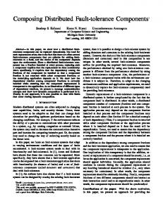
JVM Figure 1: Architecture conceptuelle de DARX tique de réplication et de gestion des fautes (ou la possible modification de celles-ci) proviennent toujours “de l’extérieur”. Le maître du groupe est chargé d’appliquer ces ordres au sein du groupe. La Figure 1 schématise l’ensemble des services qui sont mis en oeuvre pour permettre la réplication et son adaptation. • Un service de détection de défaillances qui établit la liste des serveurs participant á l’application, et notifie le système des suspicions de défaillances qui peuvent être soulevées au cours du temps. • Un service de nommage et localisation qui génère un identifiant unique pour chaque réplicat en activité dans le systéme, et retourne l’adresse d’un réplicat en réponse à une demande de localisation émanant d’un agent. • Un service d’observation système qui collecte les informations de bas niveau relatives au comportement du système distribué sous-jacent á l’application.
xv
Ces informations, une fois aggrégées et traitées, sont mises à la disposition non seulement des autres services DARX mais aussi des applications qui utilisent DARX. • Un service d’analyse applicative qui construit une représentation globale de chaque application agent supportée, et de déterminer quels sont les agents critiques ainsi que leur importance relative. • Un service de réplication qui implémente les mécanismes de réplication adaptative vis-à-vis de chaque agent. Ce service fait usage des informations fournies par l’observation système et l’analyse applicative pour redéfinir dynamiquement la stratégie appropriée et l’appliquer. • Un service d’intefaçage qui fournit les outils permettant à n’importe quelle plate-forme multi-agents de devenir tolérante aux fautes au travers de DARX. Additionnellement, ces mêmes outils permettent l’interopérabilité entre platesformes qui n’étaient pas forcément prévues pour à l’origine. Pour synthétiser, sur chaque machine hôte un serveur DARX collabore avec ses voisins pour fournir les mécanismes assurant le passage à l’échelle tels que la détection de défaillances établissant la liste des serveurs susceptibles d’être défaillants, ou la localisation et le nommage pour garantir à la fois la cohérence des informations concernant les groupes de réplications et les communications entre ces derniers. Les serveurs collaborent également dans l’observation de l’évolution de l’environnement (charge des machines, caractéristiques du réseau, . . . ), et du comportement de l’application (rôle et criticité de chaque agent, . . . ) Les informations collectées par cette observation sont ensuite réutilisées, dans un mécanisme global de décision orienté agent, afin d’adapter la politique de réplication en vigueur dans l’application multi-agents. Enfin, une interface spécifique à chaque plate-forme donne la possibilité d’encapsuler des agents de systèmes différents. Pour des raisons de portabilité et de compatibilité, DARX est écrit en Java. En effet ce langage, et plus spécifiquement la JVM, fournissent une indépendance – relative – vis-à-vis des problèmes de matériel. Or il semble sage de s’abstraire de ces
xvi
derniers en environnement distribué. De plus, un grand nombre de systèmes multiagents existants sont implémentés en Java. Enfin, l’API RMI fournit de nombreuses et utiles abstractions de haut-niveau pour l’élaboration de solutions distribuées.
Conclusion et perspectives La plate-forme présentée permet la construction d’applications fiables basées sur les systèmes multi-agents. Les caractéristiques intrinsèques de tels systèmes font que le logiciel résultant offre un degré considérable de flexibilité. Cette propriété est mise à profit pour permettre une adaptation transparente et automatisable de la tolérance aux fautes. De plus, l’architecture de DARX a été élaborée dans l’optique de garantir le passage à l’échelle. DARX a fait l’objet d’un travail d’implémentation conséquent : la réplication adaptative fonctionne pleinement et les différents services mis en oeuvre sont effectifs. Deux adaptateurs différents ont été créés, l’un pour MadKit et l’autre pour DIMA, et une application-test démontre l’interopérabilité des deux systèmes au travers de DARX. D’autres applications-tests ont été réalisées à des fins d’évaluation. Les mesures obtenues lors de ces évaluations de performances sont prometteurs ; nous travaillons donc actuellement à établir empiriquement dans quelle mesure notre architecture passe à l’échelle et quelle réactivité nous pouvons en attendre lorsque des défaillances surviennent. Il reste qu’un certain nombre d’éléments du processus de décision dans le contrôle de la réplication adaptative est à la charge du développeur applicatif. Même si DARX contribue à simplifier le développement d’applications passant à l’échelle, il n’en demeure pas moins que le rôle du développeur applicatif devrait être réduit à son minimum. C’est à notre avis la direction la plus intéressante pour poursuivre le travail effectué dans cette thèse. Nous envisageons d’entreprendre une analyse du processus d’agentification qui prendrait en compte les aspects de tolérance aux fautes au travers de la redondance de données et de processus. Une telle analyse devrait également permettre de concevoir des méthodologies pour l’insertion de la réplication adaptative dans des applications sans la nécessité préalable de disposer d’une plate-forme de support telle que DARX. Ce travail envisagé fait l’objet d’une
xvii
coopération entre les Universités du Havre (LIH), de Paris 6 (LIP6), et d’Amsterdam (IIDS/VU).
xviii
Chapitre 1 Introduction “The only joy in the world is to begin.” Cesare Pavese (1908 - 1950)
It barely seems necessary nowadays to emphasize the tremendous potential of decentralized software solutions. Their main advantage lies in the distributed nature of information, resources and action. One software engineering technique for building such software has emerged lately in the artificial intelligence research field, and appears to be both adequate and elegant: distributed agent systems.
1.1
Multi-agent systems
Intuitively, multi-agent systems appear to represent a strong basis for the construction of distributed applications. The general outline of distributed agent software consists of computational entities which interact with one another towards a common 1
2
CHAPITRE 1. INTRODUCTION
goal that is beyond their individual capabilities. It is relatively simple to comprehend the notion of a multi-agent system as a whole, with regards to the fact that such a system is conceptually related to more usual cooperative solutions [Car02][Car00]. However, there are many varying definitions of the notion of software agent. The main characteristics that seem to emerge are : • the possession of individual goals, resources and competences, • the ability to perceive and to act, to some degree, on the near environment; this includes communications with other agents, • the faculty to perform actions with some level of autonomy and/or reactiveness, and eventually to replicate, • and the capacity to provide services. The above-mentioned properties also induce that agent software proves to be adequate in the building of adaptive applications, where the relative significance of the different entities involved may be altered during the course of computation, and where this change must have an impact on the software behaviour. An example of application domain is the field of crisis management systems [BDC00] where software is developed in order to assist various teams in the process of coordinating their knowledge and actions. Possibility of failures is high and the criticality of each element, should it be an information server or an agent assistant, evolves during the management of the crisis. In addition, it is possible to specialize agents into mobile agents which can equally be executed on any location, provided the chosen host system supports the
1.2. THE RELIABILITY ISSUE
3
required agent environment. Hence, mobile agents can be relocated according to the immediate needs and preferences. This brings the multi-agent systems’ proneness to flexibility a step further. Distributing such systems over large scale networks can therefore tremendously increase their efficiency as well as their capacity, although it also brings forward the necessity of applying dependability protocols.
1.2
The reliability issue
However, it is to be noticed that most current multi-agent platforms and applications do not yet address, in a systematic way, the reliability issue [Sur00][MCM99]. The main explanation appears to be that a great majority of multi-agent systems and applications are still developed on a small scale: • they run on a single computer or on a few highly coupled – farm of – computers, • they run for short-timed experiments. As mentioned earlier, multi-agent applications rely on the collaboration amongst agents. It follows that the failure of one of the involved agents can bring the whole computation to a dead end. Replicating every agent on different hosts may allow to easily bypass this problem. In practice, this is not feasible because replication is costly, and the multiplication of the agents involved in the computation can then lead to excessive overheads. Moreover, the criticality of a software element may change at some point of the application progress. Therefore dependability protocols ought to be optimally applied when and where they are most needed. In other words, only the specific agents which are temporarily identified as crucial to the
4
CHAPITRE 1. INTRODUCTION
application should be rendered fault-tolerant, and the scheme used for this purpose should be carefully selected. Replication is the one such type of scheme that is brought forward in the context of this thesis. The reason for bringing forward the replication of data and/or computation is that it has been shown to be the only efficient way to achieve fault tolerance in distributed systems [GS97]. A replicated software component is defined as a software component that possesses a representation on two or more hosts. The consistency between replicas can be maintained following two main strategies (see Subsection 2.2.3): 1. the active one in which all replicas process all input messages concurrently, 2. and the passive one in which only one of the replicas processes all input messages and periodically transmits its current state to the other replicas. Each type of strategy has its advantages and disadvantages. The active replication provides a fast recovery delay and enables to recover from byzantine failures. This kind of technique is dedicated to critical applications, as well as other applications with real-time constraints which require short recovery delays. The passive replication scheme has a low overhead under failure free execution but does not provide short recovery delays. The choice of the most suitable strategy is directly dependent of the environment context, especially the failure rate, the kind of failure that must be tolerated, and the application requirements in terms of recovery delay and overhead. Active approaches should be chosen either if the failure rate becomes too high or if the application design specifies hard time constraints. In all other cases, passive approaches are preferable. In particular, active approaches must be
1.3. ADAPTIVE REPLICATION
5
avoided when the computational elements run on a non-deterministic basis, where a single input can lead to several different outputs, as the consistency between replicas cannot be guaranteed in this type of situation.
1.3
Adaptive replication
The work presented in this dissertation serves a twofold objective: 1. to provide efficient fault-tolerance to multi-agent systems through selective agent replication, 2. to take advantage of the specificities of multi-agent platforms to develop a suitable architecture for performing adaptive fault-tolerance within distributed applications; such applications would then be liable to operate efficiently over large-scale networks. The present dissertation depicts DARX, an architecture for fault-tolerant agent computing [MSBG01][MBS03]. As opposed to the main conventional distributed programming architectures, ours offers dynamic properties: software elements can be replicated and unreplicated on the spot and it is possible to change the current replication strategies on the fly. We have developed a solution to interconnect this architecture with various multi-agent platforms, namely DIMA [GB99] and MadKit [GF00], and in the long term to other platforms. The originality of our approach lies in two features: 1. the possibility for applications to automatically choose which computational
6
CHAPITRE 1. INTRODUCTION
entities are to be made dependable, to which degree, and at what point of the execution. 2. the hierarchic architecture of the middleware which ought to provide suitable support for large-scale applications. This dissertation is organized as follows. • Chapter 2 defines the fundamental concepts of agency and fault tolerance, and attempts to give an exhaustive overview of the current research trends in adaptive fault tolerance in general, and with respect to multi-agent systems in particular. • Chapter 3 depicts the general design of our framework dedicated to bringing adaptive fault tolerance to multi-agent systems. • Chapter 4 gives a detailed explanation of the mechanisms and heuristics used for the automation of the strategies adaptation process. • Chapter 5 reports on the performances of the software that was implemented on the basis of the solution proposed in the previous chapters. • Finally, conclusions and perspectives are drawn in Chapter 6.
Chapitre 2 Agents & Fault Tolerance “Copy from one, it’s plagiarism; copy from two, it’s research.” Wilson Mizner (1876 - 1933)
7
8
CHAPITRE 2. AGENTS & FAULT TOLERANCE
9
2.1. AGENT-BASED COMPUTING
Contents 2.1
Agent-based computing . . . . . . . . . . . . . . 2.1.1 Formal definitions of agency . . . . . . . . . . . 2.1.2 Multi-Agent Systems . . . . . . . . . . . . . . . 2.2 Fault tolerance . . . . . . . . . . . . . . . . . . . 2.2.1 Failure models . . . . . . . . . . . . . . . . . . 2.2.2 Failure detection . . . . . . . . . . . . . . . . . 2.2.2.1 Temporal models . . . . . . . . . . . . 2.2.2.2 Failure detectors . . . . . . . . . . . . 2.2.3 Failure circumvention . . . . . . . . . . . . . . 2.2.3.1 Replication . . . . . . . . . . . . . . . 2.2.3.2 Checkpointing . . . . . . . . . . . . . 2.2.4 Group management . . . . . . . . . . . . . . . 2.3 Fault Tolerant Systems . . . . . . . . . . . . . . 2.3.1 Reliable communications . . . . . . . . . . . . . 2.3.2 Object-based systems . . . . . . . . . . . . . . 2.3.3 Fault-tolerant CORBA . . . . . . . . . . . . . . 2.3.4 Fault tolerance in the agent domain . . . . . . 2.4 Conclusion . . . . . . . . . . . . . . . . . . . . . .
2.1
. . . . . . . . . . . . . . . . . .
. . . . . . . . . . . . . . . . . .
. . . . . . . . . . . . . . . . . .
. . . . . . . . . . . . . . . . . .
. . . . . . . . . . . . . . . . . .
. 9 . 10 . 12 . 18 . 19 . 20 . 21 . 22 . 24 . 24 . 30 . 34 . 36 . 36 . 38 . 40 . 44 . 47
Agent-based computing
Agent-based systems technology has generated lots of excitement in recent years because of its promise as a new paradigm for conceptualising, designing, and implementing software systems. This promise is particularly attractive for creating software that operates in environments that are distributed and open, such as the internet. The great majority of earlier agent-based systems consisted of a small number of agents running on a single host. However, as the technology matured and addressed increasingly complex applications, the need for systems that consist of multiple agents that communicate in a peer-to-peer fashion has become apparent.
10
CHAPITRE 2. AGENTS & FAULT TOLERANCE
Central to the design and effective operation of such multiagent systems (MASs) are a core set of issues and research questions that have been studied over the years by the distributed AI community. The present section aims at defining the various concepts, extracted from current research in the multiagent systems domain, which are used as a basis for the work undergone in the context of this thesis.
2.1.1
Formal definitions of agency
Defining an agent is a complex matter; and even though it has been debated for several years, the discussion still remains close to that of a theological issue. As pointed by Carl Hewitt1 , the question “What is an agent?" is embarrassing for the agent-based computing community in just the same way that the question “What is intelligence?" is embarrassing for the mainstream AI community. Ferber attempts in [Fer99] to give a rigorous description of agents. “An agent is a physical or virtual entity: 1. which is capable of acting in an environment. 2. which can communicate directly with other agents. 3. which is driven by a set of tendencies – in the form of individual objectives or of a satisfaction/survival function which it tries to optimise. 4. which possesses resources of its own. 1
At the 13th international workshop on Distributed AI.
2.1. AGENT-BASED COMPUTING
11
5. which is capable of perceiving its environment – but to a limited extent. 6. which has only a partial representation of its environment – and perhaps none at all. 7. which possesses skills and can offer services. 8. which may be able to reproduce itself. 9. whose behaviour tends towards satisfying its objectives, taking account of the resources and skills available to it and depending on its perception, its representation and the communications it receives." Note that agents are capable of acting, not just reasoning. Actions affect the environment which, in turn, affects future decisions of agents. A key property of agents is autonomy. They are, at least to some extent, independent. Their code does not entirely predetermine their actions; they can make decisions based on information extracted from their environment or obtained from other agents. One can say that agents have "tendencies". Tendencies is a deliberately vague term. Tendencies could be individual goals to be achieved, or the optimisation of some satisfaction-based function. Given that the author of the present dissertation considers himself to be an MAS user rather than an AI expert, and that fault tolerance in distributed systems is the actual scope of this thesis, a weaker notion of agency is adopted. It is loosely based on the definition given in [WJ95] and construes agents as virtual entities which have the following properties: 1. Autonomy. An agent possesses individual goals, resources and competences;
12
CHAPITRE 2. AGENTS & FAULT TOLERANCE
as such it operates without the direct intervention of humans or others, and has some kind of control over its actions and its internal state2 – including the faculty to replicate. 2. Sociability. An agent can interact with other agents – and possibly humans – via some kind of agent communication language [GK97]. Through this means, an agent is able to provide services. 3. Reactivity. An agent perceives and acts, to some degree, on its near environment; it can respond in a timely fashion to changes that occur around it. 4. Pro-activeness. Although some agents – called reactive agents – will simply act in response to their environment, an agent may be able to exhibit goal-directed behaviour by taking the initiative. A simple way of conceptualising an agent is thus as a software component whose behaviour exhibits the properties listed above.
2.1.2
Multi-Agent Systems
Once the notion of agent is clarified, one needs to define the system which will encompass agent computations and interactions. Hence appears the notion of multiagent system (MAS). [DL89] defines a multi-agent system as a “loosely coupled network of problem solvers that interact to solve problems that are beyond the individual capabilities 2
A strong component of agent autonomy is agent adaptivity; the control an agent has over itself allows it to regulate its abilities without any exterior assistance.
2.1. AGENT-BASED COMPUTING
13
or knowledge of each problem solver ". These problem solvers, often called agents, are autonomous and can be heterogeneous in nature. [DC99] gives a more actual definition of MASs as “a set of possibly organised agents which interact in a common environment". According to [Syc98], the characteristics of MASs are that: 1. each agent has incomplete information or capabilities for solving the problem and, thus, has a limited viewpoint; 2. there is no system global control; 3. data are decentralised; 4. computation is asynchronous. As befits its goal of fixing rigorous definitions, [Fer99] provides a strict interpretation of the term multi-agent system as being applied to systems comprising the following elements: • An environment E, that is, a space which generally has volume. • A set of objects, O. These objects are situated, that is to say, it is possible at a given moment to associate any object with a position in E. • An assembly of agents, A, which are specific objects – a subset of O –, represent the active entities in the system. • An assembly of relations, R, which link objects – and therefore, agents – to one another. • An assembly of operations, Op, making it possible for the agents of A to perceive, produce, transform, and manipulate objects in O.
14
CHAPITRE 2. AGENTS & FAULT TOLERANCE
• Operators with the task of representing the application of these operations and the reaction of the world to this attempt at modification, which we shall call the laws of the universe. There are two important special cases of this general definition. 1. Purely situated agents. An example would be robots. In this case E – the environment – is Euclidean 3-space, A are the robots, and O not only other robots but physical objects such as obstacles; these are situated agents. 2. Purely communicating agents. If A = O and E is empty, then the agents are all interlinked in a communication networks and communicate by sending messages, we have a purely communicating MAS. The second type of agents is the most fitting as a paradigm for building distributed software. Hence thework presented in the context of this thesis focuses on purely communicating agents. [Fer99] also identifies three types of models which constitute the basis for building MASs: 1. The agent model determines agent behaviour; thus it provides meaningful explanations for all agent actions, and gives an invaluable insight on how to access and comprehend the internal state of an agent when there is one. Two categories of agents can be distinguished: reactive agents and cognitive agents. Reactive agents are limited to following stimulus/response laws; they allow to determine behaviours in an accurate way, yet they don’t possess an internal state – and therefore cannot build nor update any representation of
2.1. AGENT-BASED COMPUTING
15
their environment. Conversely, cognitive agents do comprise an internal state and can establish a representation of their environment. 2. The interactions model describes how agents exchange information in order to reach a common goal [GB99]. Hence interactions models are potentially more important than agent models for MAS dynamics. For instance, depending upon the instated interactions model, agents will either communicate directly by exchanging messages, or indirectly by acting on their environment. 3. The organisational model is the component which transforms a set of independent agents into a MAS; it provides a framework for agent interactions through the definition of roles, behaviour expectations, and authority relations. Organisations are, in general, conceptualized in terms of their structure, that is, the pattern of information and control relations that exist among agents and the distribution of problem solving capabilities among them. In cooperative problem solving, for example [CL83], a structure gives each agent a high-level view of how the group solves problems. The organisational model should also indicate the connectivity information to the agents so they can distribute sub-problems to competent agents. In open-world environments, agents in the system are not statically predefined but can dynamically enter and exit an organisation, which necessitates mechanisms for locating agents. This task is challenging, especially in environments that include large numbers of agents and that have information sources, communication links, and/or agents that might be appearing and disappearing. Another perspective in multiagent systems research defines organisation less in
16
CHAPITRE 2. AGENTS & FAULT TOLERANCE
terms of structure and more in terms of current organisation theory. An organisation then consists of a group of agents, a set of activities performed by the agents, a set of connections among agents, and a set of goals or evaluation criteria by which the combined activities of the agents are evaluated. The organisational structure imposes constraints on the ways the agents communicate and coordinate. Examples of organisations that have been explored in the MAS literature include the following: • Hierarchy: The authority for decision making and control is concentrated in a single problem solver – or specialised group – at each level in the hierarchy. Interaction is through vertical communication from superior to subordinate agent, and vice versa. Superior agents exercise control over resources and decision making. • Community of experts: This organisation is flat; each problem solver is a specialist in some particular area. The agents interact by rules of order and behaviour [LS93]. Agents coordinate though mutual adjustment of their solutions so that overall coherence can be achieved. • Market: Control is distributed to the agents that compete for tasks or resources through bidding and contractual mechanisms. Agents interact through one variable, price, which is used to value services [MW96][DS83]. Agents coordinate through mutual adjustment of prices. • Scientific community: This is a model of how a pluralistic community could operate [KH81]. Solutions to problems are locally constructed, then they are communicated to other problem solvers that can test, challenge, and refine the solution [Les91].
2.1. AGENT-BASED COMPUTING
17
The motivations for the increasing interest in MAS research include the ability of MASs to do the following: • to solve problems that are too large for a centralised agent because of resource limitations or the sheer risk of having one centralised system that could be a performance bottleneck or could fail at critical times. • to allow for the interconnection and interoperation of multiple existing legacy systems; this can be done, for example, by building an agent wrapper around the software to allow its interoperability with other systems [GK97]. • to provide solutions to problems that can naturally be regarded as a society of autonomous interacting components/agents; for example, in meeting scheduling, a scheduling agent that manages the calendar of its user can be regarded as autonomous and interacting with other similar agents that manage calendars of different users [GS95]. • to provide solutions that efficiently use information sources that are spatially distributed; examples of such domains include sensor networks [CL83], seismic monitoring [MJ89], and information gathering from the internet [SDP+ 96]. • to provide solutions in situations where expertise is distributed; examples of such problems include concurrent engineering [LS93], health care, and manufacturing. • to enhance performance along the dimensions of – computational efficiency because concurrency of computation is exploited,
18
CHAPITRE 2. AGENTS & FAULT TOLERANCE
– reliability in cases where agents with redundant capabilities or appropriate interagent coordination are found dynamically, – extensibility because the number and the capabilities of agents working on a problem can be altered, – maintainability because the modularity of a system composed of multiple components-agents makes it easier to maintain, – responsiveness because modularity can handle anomalies locally, not propagate them to the whole system, – flexibility because agents with different abilities can adaptively organise to solve the current problem, – reuse because functionally specific agents can be reused in different agent teams to solve different problems.
2.2
Fault tolerance
Fault tolerance has become an essential part of distributed systems. As the number of sites involved in computations grows, as the execution duration of distributed software increases, failure occurences become ever more probable. Without appropriate responses, there is little chance that highly distributed applications will produce a valid result. A considerable strength of distributed systems lies in the fact that, while several system components may fail, the remaining components will stay operational. Fault tolerance endeavours to exploit this fact in order to ensure the continuity of computations.
2.2. FAULT TOLERANCE
19
Fault tolerance has widely been researched, essentially in local networks, and more recently in large scale networks. This section aims at synthesising the main algorithms and techniques for fault tolerance.
2.2.1
Failure models
Fault-tolerant systems are characterised by the type of failures they allow to tolerate. Failures affecting a resource may be classified by associating them to the error that arises. Four types of failures can thus be distinguished: 1. Crash failure. Such a failure is consequence of a fail-stop fault, that is a fault which causes the affected component to stop. A crash failure can be seen as a persistent omission failure. 2. Omission failure. A transient failure such that no service is delivered at a given point of the computation. It is instantaneous and will not affect the ulterior behaviour of the affected component. 3. Timing failure. Such a failure occurs when a process or service is not delivered or completed within the specified time interval. Timing faults cannot occur if there is no explicit or implicit specification of a deadline. Timing faults can be detected by observing the time at which a required interaction takes place; no knowledge of the data involved is usually needed. Since time increases monotonously, it is possible to further classify timing faults into early, late, or “never" (omission) faults. Since it is practically impossible to determine if “never" occurs, omission faults are really late timing faults that exceed an arbitrary limit.
20
CHAPITRE 2. AGENTS & FAULT TOLERANCE
4. Arbitrary failure. A failure is said to be arbitrary when the service delivered by the affected component deviates from its pre-defined specifications enduringly. An example of arbitrary failure is the byzantine failure where the affected component shows a malicious behaviour.
Faults affecting a specific execution node are often designated by use of the following terminology:
• Either the faulty node stops correctly and suspends its message transmissions; in this case, the node is considered fail-silent [Pow92]. This equates to a crash failure.
• Or the node shows an unexpected behaviour resulting from an arbitrary failure; the node then gets considered as fail-uncontrolled [Pow92]. Typical behaviours include: omission to send part of the expected messages, emission of additional – unexpected – messages, emission of messages with erroneous contents, refusal to receive messages.
2.2.2
Failure detection
Failure detection is an essential aspect of fault-tolerant solutions. The quality of the failure diagnoses as well as the speed of the failure recoveries rely heavily on failure detection.
2.2. FAULT TOLERANCE
2.2.2.1
21
Temporal models
Failure detection mechanisms within a distributed system differ according to the temporal model in use. Temporal models are based on hypotheses that are made with respect to bounds on both processing and communication delays. Three types of models can be discerned: 1. EBD (Explicitly Bounded Delays) model: bounds on processing and communication delays exist, and their values are known a priori. 2. IBD (Implicitly Bounded Delays) model: bounds on processing and communication delays exist, yet their values are unknown. 3. UBD (UnBounded Delays) model: there are no bounds either on processing or on communication delays. Assuming a model has an impact on the solutions that can be deployed for a specific problem. For instance there are probabilistic solutions for ditributed consensus in all models [FLP85][CT96], yet deterministic solutions can only assume either the EBD [LSP82][Sch90] or the IBD model [DDS87][DLS88]. In parallel two approaches are often distinguished: 1. The synchronous approach uses the same hypotheses on delays as the EBD model [HT94]. It is also assumed that: (a) every process possesses a logical clock which presents a bounded drift with respect to real time,
22
CHAPITRE 2. AGENTS & FAULT TOLERANCE
(b) and there exist both a minimum and a maximum bound on the time it takes a process to execute an instruction. 2. The asynchronous approach uses the same hypotheses on delays as the UBD model.
2.2.2.2
Failure detectors
In the synchronous model, detecting failures is a trivial issue. Since delays are bounded and known, a simple timeout enables to tell straight away if a failure has occured. Whether it is a timing or a crash failure depends on the failure model considered. The asynchronous model forbids such a simple solution. Fisher, Lynch, and Paterson [FLP85] have shown that consensus3 cannot be solved deterministically in an asynchronous system that is subjected to even a single crash failure. This impossibility results from the inherent difficulty of determining whether a remote process has actually crashed or whether its transmissions are being delayed for some reason. In [CT96], Chandra and Toueg introduce the unreliable failure detector concept as a basic building block for fault-tolerant distributed systems in an asynchronous environment. They show how, by introducing these detectors into an asynchronous system, it is possible to solve the Consensus problem. Failure detectors can be seen as one oracle per process. An oracle provides a list of processes that it currently suspects of having crashed. Many fault-tolerant algorithms have been proposed [GLS95] [DFKM97] [ACT99] based on unreliable 3
Consensus is the “greatest common denominator” of agreement problems such as atomic broadcast or atomic commit.
2.2. FAULT TOLERANCE
23
failure detectors, but there are few papers about implementing these detectors [LFA00] [SM01] [DT00]. Chandra and Toueg also elaborate a method for the classification of failure detectors. They define two properties, refined into subproperties, for this purpose: 1. Completeness. There is a time after which every process that crashes is permanently suspected. • Strong completeness. Eventually every process that crashes is permanently suspected by every correct process. • Weak completeness. Eventually every process that crashes is permanently suspected by some correct process. 2. Accuracy. There is a time after which some correct process is never suspected by any correct process. • Strong accuracy. No process is suspected before it crashes. • Weak accuracy. Some correct process is never suspected. • Eventual strong accuracy. There is a time after which correct processes are not suspected by any correct process. • Eventual weak accuracy. There is a time after which some correct process is never suspected by any correct process. "A failure detector is said to be Perfect if it satisfies strong completeness and strong accuracy. The set of all such failure detectors, called the class of Perfect failure detectors, is denoted by P. Similar definitions arise for each pair of
24
CHAPITRE 2. AGENTS & FAULT TOLERANCE
completeness and accuracy properties. There are eight such pairs, obtained by selecting one of the two completeness [sub]properties and one of the four accuracy [sub]properties [. . . ] The resulting definitions and corresponding notations are given in [Table 2.1]." [CT96] Table 2.1: Failure detector classification in terms of accuracy and completeness Completeness Strong Weak
Strong Perfect P Quasi-perfect Q
Accuracy Weak Eventually strong Strong Eventually perfect S 3P Weak Eventually quasi-perfect W 3Q
Eventually weak Eventually strong 3S Eventually weak 3W
Two major theoretical results are directly extracted from this work. In [CT91] Chandra, Hadzilacos and Toueg show that consensus can be solved using a 3W detector. Furthermore [CHT92] demonstrates that the latter is the "weakest" detector suitable for this purpose. Chandra and Toueg also prove in [CT96] that, using a detector that satisfies weak completeness, it is possible to build a detector that satisfies strong completeness.
2.2.3
Failure circumvention
Several ways to work around failures have been devised for distributed systems. The present Subsection aims at presenting the two main solutions.
2.2.3.1
Replication
Replication of data and/or computation on different nodes is the only means by which a distributed system may continue to provide non-degraded service in the
2.2. FAULT TOLERANCE
25
presence of failed nodes [GS97]. Even though stable storage can be used to allow the system to recover – eventually – from node failures and can thus be thought of as a means for providing fault-tolerance, such a technique used alone does not allow distributed system architectures to achieve higher availability than a non-distributed system. In fact, if a computation is spread over multiple nodes without any form of replication, distribution can only lead to a decrease in dependability since the computation may only proceed if each and every node involved is operational. The basic unit of replication considered here is that of a software component. A replicated software component is defined as a software component that possesses a representation on two or more nodes. Each representation will be referred to as a replica of the software component. The degree of replication of software components in the system depends primarily on the degree of criticality of the component but also on how complex it is to add new members to an existing group. In general it is wise to envisage groups of varying size, even though the degree of replication may often be limited to 2 or 3 – or even 1, that is no replication, for non-critical components. Two basic techniques for replica coordination can be identified according to the degree of replica synchronization: • Active replication (see Figure 2.1) is a technique in which all replicas process all input messages concurrently so that their internal states are closely synchronized in the absence of faults, outputs can be taken from any replica. • Passive replication (see Figure 2.2) is a technique in which only one of the replicas – the primary – processes the input messages and provides output
26
CHAPITRE 2. AGENTS & FAULT TOLERANCE
S3 S2 reply
S1 request
Client Figure 2.1: Active replication
S3 S2 backup
S1 request
reply
Client Figure 2.2: Passive replication
27
2.2. FAULT TOLERANCE
messages. In the absence of failures, the other replicas – the standbies – remain inactive; their internal states are however regularly updated by means of checkpoints from the primary.
S3 S2 notification
S1 request
reply
Client Figure 2.3: Semi-active replication A third technique, Semi-active replication (see Figure 2.3) can be viewed as a hybrid of both active and passive replication. It was introduced in [Pow91] to circumvent the problem of non-determinism with active replication; while the actual processing of a request is performed by all replicas, only one of them – the leader – performs the non-deterministic parts of the processing and provides output messages. In the absence of failures, the other replicas – the followers – may process input messages but will not produce output messages; depending on whether any non-deterministic computations were made, their internal state is updated either by direct processing of input messages, or by means of "mini-checkpoints" from the leader. Another variation is the Semi-passive replication technique [DSS98], where a client sends its request to all replicas and every replica will send a response back to the client, yet only one replica actually performs the processing in the absence of failures.
28
CHAPITRE 2. AGENTS & FAULT TOLERANCE
Active replication allows to circumvent any type of failure. More specifically it is the only technique with which arbitrary failures may be foiled: one such way is to cast a vote on the output of the replicas. The main advantage of active replication is that failure recovery is near to instantaneous since all replicas are kept in the same state. However the active technique mobilises an important amount of computing resources: every replica drains on its supporting host, and duplicating the communications adds to the network load. Moreover, active replication is only applicable to deterministic processes, lest the replicas start diverging. Since it provides fast failure recovery, this type of replication is most suitable for environments where bounded response delays are required. The primary is the only active replica in the passive technique. If the primary fails, one of the standbies will take its place and compute from the point when the last update was sent. Passive replication is somewhat similar to techniques based on stable storage [BMRS91][PBR91]; the standbies serve as backup equivalents. A considerable number of checkpointing techniques [EZ94][CL85][Wan95][SF97][EJW96] have been devised and can be used alongside passive replication. The advantage of the passive replication over the active one is that it is less resource consuming in the absence of failures, and therefore more efficient. Indeed no computation is required on nodes hosting a standby. Moreover this approach does not require that the processes show a deterministic behaviour. However these advantages ought to be put into perspective as both the process of determining consistent checkpoints and that of the recovery handling through rollbacks may prove to be costly. Passive replication is often favoured for environments where failures are rare and where time constraints are not too strong, such as loosely connected networks of worksta-
29
2.2. FAULT TOLERANCE
tions. It can be noted that this technique got used in high-profile projects such as Delta-4 [Pow91], Mach [Bab90], Chorus [Ban86] and Manetho [EZ94]. Semi-active replication aims at blending the advantages of the above mentioned techniques: enable to handle non-deterministic processes while preserving satisfactory performances in recovery phases. Input messages are forwarded by the leader to its followers so that requests get independently processed by every replica; non-deterministic decisions are enforced upon the followers through notifications or "mini-checkpoints" from the leader. Unlike the active technique, the semi-active one doesn’t require input messages to be delivered in the same order: the leader imposes its request processing order on its followers through notifications upon every message reception. Since it combines the benefits of the two other techniques, semi-active replication is an interesting approach. Based on [Pow91], table 2.2 sums up the properties of the three replication techniques described above: Table 2.2: Comparison of replication techniques Repl. technique Active Passive Semi-active
Recovery overhead Lowest Highest Low
Non-determinism Forbidden Allowed Resolved
Accomodated failures Silent / Uncontrolled Silent Silent4
The choice of the replication technique is a delicate matter. Although it is obvious that passive replication is not suitable for real-time environments, several criteria must be assessed in all the other cases: • processing overhead, 4
[Pow94] claims that an extension of the semi-active replication technique allows to accomodate fail-uncontrolled behaviour.
30
CHAPITRE 2. AGENTS & FAULT TOLERANCE
• communications overhead, • the considered failure model, • and the execution behaviour of the supported application. Aside from the three basic techniques, other replication schemes have been devised. Two examples are: • Coordinator-cohort replication [Bir85] is a variation on the semi-active replication, a hybrid of both the active and passive techniques; every replica gets to receive the input messages, yet only the coordinator takes care of request handling and message emissions. • Semi-passive replication [DSS98] differs from the passive technique in the choice of the primary replica. Unlike the passive replication where the primary gets chosen by the client, semi-passive replication solves this matter through automatic handling amongst the replicas: an election takes place using a consensus algorithm over failure detectors. This allows transparency of the failure handling and therefore faster recovery delays.
2.2.3.2
Checkpointing
Checkpointing is a very common scheme for building distributed software that may recover from failures. Its basic principle is to back up the system state on stable storage at specific points of the computation, thus allowing to restart the latter when transient faults occur. Although checkpointing is both a vast subject and a very important part of fault tolerance, the scope of this thesis tends to be more specific
2.2. FAULT TOLERANCE
31
about replication. Hence the ensuing description of checkpointing techniques is kept to the essential. Two types of recovery techniques based on checkpoints may be distinguished: independent and coordinated checkpointing. Independent checkpointing. Processes perform checkpoints independently, and synchronise during the recovery phase. This kind of technique has the advantage of minimising overheads in failure-free environments. However failure occurences reveal the main downside of independent checkpointing: rolling back every process to its last checkpoint may not suffice for ensuring a consistent global state [CL85]. For instance if a process crashes after sending a message and if the last checkpoint was made before the emission, then the request becomes orphaned. This may cause inconsistencies where the receiver of the orphan message has handled a request which the sender, once it is restarted, has not emitted yet. Thus it can be necessary to roll the receiving process back to a previous state in which the problematic request wasn’t yet received. This can easily lead to a domino effect where several processes need to roll way back in order to attain global state consistency. Figure 2.4 shows an example of a domino effect. Respectively, Xs and arrows represent checkpoints and messages. Given the point where process P fails, it must be restarted from Cp2 . Yet this implies that message m6 becomes orphaned, and therefore process Q must be restarted from Cq2 . Message m7 then becomes orphaned too and process R will have to be restarted from Cr1 . The whole rollback process ends by restarting all processes from their initial checkpoints. An extension of independent checkpointing has been designed in order to limit
32
CHAPITRE 2. AGENTS & FAULT TOLERANCE
P
C p0
Cp
1
Cp
2
X
X
X
m2
Q
m6
m4
Cq
0
Cq
1
Cq
X
X
X
m1
2
m5
m
3
R
Failure
C 0r
C 1r
X
X
m7
Figure 2.4: Domino effect example domino effects by means of communications analysis: message logging. There are two main logging algorithm categories: 1. Pessimistic logging algorithms [PM83][SF97] record communications synchronously so as to prevent any domino effect, at the same time increasing the computation overheads and improving recovery speeds. 2. Optimistic logging algorithms [SY85][SW89][JZ87] strive to limit overheads linked to log access both by reducing the amount of data to back up and by doing so asynchronously. Coordinated checkpointing. Processes coordinate when checkpointing so as to improve recovery in the presence of failures. There two main ways of coordinating processes for checkpointing: 1. Explicit synchronisation. The basic algorithm consists in suspending all processes while performing a global checkpoint. In order to reduce the la-
33
2.2. FAULT TOLERANCE
Table 2.3: Checkpointing techniques comparison Non coord. Comm. Overhead Backup Overhead Nb. of checkpoints Recovery Domino effect
Weak Weak Several Complex Possible
Coordinated Expl. Impl. None Weak Highest Weak One One Simple Simple Impossible Impossible
Logging Pess. Opt. Highest High Weak Weak One Several Simple Complex Impossible Impossible
tency overhead this algorithm induces, non-blocking variations have been designed [CL85][LY87] where processes may keep exchanging messages while checkpointing as well as a selective variation [KT87] which limits the number of involved processes. 2. Implicit synchronisation. Also known as lazy coordination [BCS84], it consists in dividing the process executions into recovery intervals and in adding timestamps to application messages with respect to their corresponding interval. It has the advantage of shunning latency overheads, yet the number of memorised checkpoints increases considerably. Based on a similar assessment from [EJW96], table 2.3 sums up the various checkpointing techniques and establishes a quick comparison of their main features. Non coordinated checkpointing has the lowest overheads but may generate domino effects; handling the domino effect either by coordinating checkpoints or by logging messages has an impact in terms of execution overheads. Coordinated checkpointing appears worthwhile for environments where failures occur seldom. More specifically, the implicit approach is less costly in general. However both approaches give rise to two main issues: (i) the number of checkpoints increases rapidly in situations where consistency is problematic, and (ii) interactions with the outside world raise complex
34
CHAPITRE 2. AGENTS & FAULT TOLERANCE
difficulties. Message logging algorithms induce high communication overheads; this can considerably slow the computation. Yet their main advantages are that (i) checkpoints can be independent, (ii) faulty processes alone require to be rerun, and (iii) interactions with the outside world can easily be dealt with.
2.2.4
Group management
Fault tolerant support is generally based on the notion of group; groups of processes cooperate in order to handle the tasks of a single software component. A process can join or leave a group at any point. The group view vi (G) is the set of processes that represent software component G. Although the view may evolve, all the members of group G share the same sequence of views. In order to implement these views, a group membership service is necessary, preferably supported by a failure detection service. Multicast – the sending of any message m to group G – may call for various semantics:
1. Reliable broadcast guarantees that m will be received either by all members of G or by none. This type of diffusion does not bear any assurance over the order in which messages will get received. 2. Virtual synchrony, introduced in [BJ87], guarantees that if a process switches from view vi (G) to view vi+1 (G) as a result of handling request m, than every process included in view vi (G) will handle request m before proceeding to the next view. Messages are therefore ordered with respect to the views they are
2.2. FAULT TOLERANCE
35
associated to. However, within a same view, no message processing order is guaranteed. The virtual synchrony model is often extended with semantics on message ordering: • FIFO ordering guarantees that the ordering of messages from a single sender will be preserved. • Causal ordering guarantees that the order in which messages are received will reflect the causal emission order. That is: if the broadcast of a message mi causally precedes the broadcast of a message mi+1 , then no correct process delivers mi+1 unless it has previously delivered mi . • Total ordering guarantees that the order in which messages are received is the same for all group members.
36
CHAPITRE 2. AGENTS & FAULT TOLERANCE
2.3
Fault Tolerant Systems “Success is the ability to go from one failure to another with no loss of enthusiasm.” Sir Winston Churchill (1874 - 1965)
Systems designed to enable fault tolerance in distributed environments are quite numerous nowadays. This Section aims at presenting the main architectures designed for bringing fault tolerance in distributed software.
2.3.1
Reliable communications
A first type of software toolkit for implementing fault-tolerant applications focuses on reliable communications amongst groups. Isis is one of those; it consists of a set of procedures which, once called in the developed client programs, allow to handle group membership for processes. Multicasts diffusions amongst the process groups are provided along with ranges of guarantees on atomicity and the order in which messages are delivered. Isis was the first platform that assumed the virtual synchrony model [BvR94] where diffusions are ordered with respect to views (see Subsection 2.2.4). Isis introduces the concept of primary partition: if a group becomes partitioned, then only the partition with a majority of members may continue its execution. However such a solution can lead to deadlocks if no primary partition emerges. Initiated as a redesign of the Isis group communication system, the Horus project [vRBM96] evolved beyond these initial goals, becoming a sophisticated group
2.3. FAULT TOLERANT SYSTEMS
37
communication system with an emphasis and properties considerably different from those of its "parent" system. Broadly, Horus is a flexible and extensible processgroup communication system, in which the interfaces seen by the application can be varied to conceal the system behind more conventional interfaces, and in which the actual properties of the groups used – membership, communication, events that affect the group – can be matched to the specific needs of the application. If an application contains multiple subsystems with differing needs, it can create multiple superimposed groups with different properties in each. The resulting architecture is completely adaptable, and reliability or replication can be introduced in a wholly transparent manner. Horus protocols are structured in generic stacks, hence new protocols can be developed by adding new layers or by recombining existing ones. Through dynamic run-time layering, Horus permits an application to adapt the protocols it runs to the environment in which it finds itself. Existing Horus protocol layers include an implementation of virtually synchronous process groups, protocols for parallel and multi-media applications, as well as for secure group computing and for real-time applications. Ensemble [RBD01], an ML implementation of Horus, allows to interface software written in various programming languages. More importantly it enables to support complex semantics by combining simple layers, and to perform automatic verifications. Additionally, Horus distinguishes itself from Isis in the fact that minority partitions may continue their execution, giving way to multiple concurrent group views. The issue raised by this approach is the partition merging which can be complex, especially if irreversible operations have occurred. Two other platforms, Relacs [BDGB95] and Transis [MADK94], adopt a similar model allowing concur-
38
CHAPITRE 2. AGENTS & FAULT TOLERANCE
rent views; although Relacs imposes restrictions on the creation of new views. The Phoenix toolkit [Mal96] is yet another platform for building fault tolerant applications by means of group membership services and diffusion services. It also uses the virtual synchrony paradigm. Its originality is to specialise in large-scale environments where replicated processes can be very numerous and very distant from one another. One noticeable aspect of Phoenix is that it handles process groups, conversely to other toolkits such as Horus and Transis which handle groups of nodes; this aspect adds to the scalability of the solution. Phoenix is based on an intermediate approach between that of primary partitions in Isis and that of concurrent partitions in Horus and Relacs: it proposes an unstable failure suspicion model where a failed suspected host can be reconsidered alive. Minority partitions may continue their execution, but their state will be overwritten by that of the primary partition if it reappears.
2.3.2
Object-based systems
A second type of framework for fault-tolerant computing uses the object paradigm. Arjuna [PSWL95] applies object-oriented concepts to structures for tolerating physical faults. Imbricated atomic actions are enacted upon persistent objects. Arjuna makes use of the specialisation paradigm: thus application objects can inherit persistence and recovery abilities. The client-server model is applied: servers handle the objects and invocations are requested by the clients. Arjuna deals with crashsilent failures. When a failure occurs, two cases may arise: 1. The client has crashed. The server becomes orphaned and might await the
2.3. FAULT TOLERANT SYSTEMS
39
next client request indefinitely; to avoid such a situation, servers check the liveness of their clients regularly. 2. The server has crashed. The client will become aware of the failure upon the next object invocation.
The aim of the GARF project [Maz96][GGM94] is to design and to implement software that automatically generates a distributed fault-tolerant application from a centralised one. GARF is implemented in SmallTalk on top of Isis. Each object of the original application gets wrapped in an encapsulator and coupled to a mailer, thus allowing its transparent replication supported by a GARF-specific runtime. Each {encapsulator, mailer} pair can be viewed as a replication strategy. Strategies can therefore be customized by specialising the generic classes; indeed several off-the-shelf strategies are already provided in GARF: active, passive, semi-passive and coordinator-cohort. GARF uses the reflection properties of SmallTalk to make the fault tolerance features adaptive; strategies can be switched and the replication degree can be altered at runtime. Finally, [FKRGTF02] brings reflection a step further than GARF by introducing a meta-model expressed in terms of object method invocations and data containers defined for objects’ states. It enables both behavioural and structural reflection. Supported applications comprise two levels: the base-level which executes application components, and the meta-level which executes components devoted to the implementation of non-functional aspects of the system – for instance faulttolerance. Both levels of the architecture interact using a meta-object protocol (MOP), and base-level objects communicate by method invocations. Every request
40
CHAPITRE 2. AGENTS & FAULT TOLERANCE
received by an object can be intercepted by a corresponding meta-object. This interception enables the meta-object to carry out computations both before and after the method invocation. The meta-object can, for instance, authorize or deny the execution of the target method. Then, using behavioural intercession, the meta-object can act on its corresponding base-level object to trigger the execution of the intercepted method invocation. Additionally, structural information regarding inheritance links and associations between classes is included in a structural view of the base-level objects; this can be used to facilitate object state checkpointing. Meta-objects can obtain and modify this information when necessary using the MOPÕs introspection facilities. This approach is implemented in FRIENDS [FP98], a CORBA-compliant MOP with adaptive fault tolerance mechanisms.
2.3.3
Fault-tolerant CORBA
Object-based distributed systems are ever more commonly designed in compliance with the OMG’s CORBA standards, providing features which include localisation transparency, interoperability and portability. A CORBA specification for fault tolerance [OMG00] appeared in April 2000. It introduces the notion of object groups: an object may be replicated within a group with fault tolerance attributes such as the replication strategy5 or the minimum and maximum bounds for the replication degree. The attributes are associated to the group upon its creation, yet it is also possible to modify them dynamically afterwards. Such groups allow transparent replication; a client invoking methods of the replicated object is made aware neither 5
Four strategies are proposed, ranging from purely active replication to primary-based passive replication.
2.3. FAULT TOLERANT SYSTEMS
41
of the strategy in use nor of the members involved. OMG also proposes a notion specific to scalability issues: that of domains which possess their associated replication manager. The existing fault-tolerant CORBA implementations rely on group communication services, such as membership and totally ordered multicast, for supporting consistent object replication. The systems differ mostly at the level at which the group communication support is introduced. Felber classifies in [Fel98] existing systems based on this criterion and identifies three design mainstreams: integration, interception and service.
1. With the integration approach, the ORB is augmented with proprietary group communication protocols. The augmented ORB provides the means for organizing objects into groups and supports object references that designate object groups instead of individual objects. Client requests made with object group references are passed to the underlying group communication layer which disseminates them to the group members. The most prominent representatives of this approach are Electra [LM97] and Orbix+Isis [ION94]. Orbix+Isis was the first commercial system to support fault-tolerant CORBA-compliant application building. Electra tolerates network partitions and timing failures, it also supports dynamic modifications of the replication degree. Several implementations of Electra have been made above Isis, Horus and Ensemble. 2. With the interception approach, no modification to the ORB itself is required. Instead, a transparent interceptor is over-imposed on the standard operating system interface – system calls. This interceptor catches every call made by
42
CHAPITRE 2. AGENTS & FAULT TOLERANCE
the ORB to the operating system and redirects it to a group communication toolkit if necessary. Thus every client operation invoked on a replicated object is transparently passed to a group communication layer which multicasts it to the object replicas. The interception approach was introduced and implemented by the Eternal system [MMSN98]: IIOP messages get intercepted and redirected to Totem [MMSA+ 96]. 3. With the service approach, group communication is supported through a welldefined set of interfaces implemented by service objects or libraries. This implies that in order for the application to use the service it has to either be linked with the service library, or pass requests to replicated objects through service objects. Thus DOORS [NGSY00] proposes a CORBA-compliant fault tolerance service which concentrates on flexibility by leaving both the detection and the recovery strategies under the responsibility of the application developer. FTS-ORB [SCD+ 97] provides an FT service based on checkpointing and logging; however it handles neither failure detection nor recovery. The service approach was also adopted by the Object Group Service (OGS) [Fel98] [FGS98] in the context of the EPFL Nix project.
Among the above approaches, the integration and interception approaches are remarkable for their high degree of object replication transparency: it is indistinguishable from the point of view of the application programmer whether a particular invocation is targeted to an object group or to a single object. However, both of these approaches rely on proprietary enhancements to the environment, and hence are platform-dependent: with the integration approach, the application code uses
43
2.3. FAULT TOLERANT SYSTEMS
proprietary ORB features and therefore, is not portable; whereas with the interception approach, the interceptor code is not portable as it relies on non standard operating system features. The service approach is less transparent compared to the other two. However, it offers superior portability as it is built on top of an ORB and therefore, can be easily ported to any CORBA compliant system. Another strong feature of this approach is its modularity. It allows for a clean separation between the interface and the implementation and therefore matches object-oriented design principles and closely follows the CORBA philosophy. Two
more
recent
proposals,
Interoperable
Replication
Logic
(IRL) [MVB01] and the CORBA fault-tolerance service (FTS) [FH02], do not clearly fall in any one of the above categories. IRL proposes to introduce a separate tier which supports replication; hence transparency and flexibility are preserved as it involves only minimal changes to the existing clients and object implementations. The core idea of the FTS proposal is to utilize the standard CORBA Portable Object Adaptor (POA) for extending ORBs with new features such as fault-tolerance. The resulting architecture combines the efficiency of the integration approach with the portability and the interoperability of the service approach. Aquarius [CMMR03] integrates both these approaches, the latter for implementing the server side of the replication support.
44
CHAPITRE 2. AGENTS & FAULT TOLERANCE
2.3.4
Fault tolerance in the agent domain
Within the field of multi-agent systems, fault tolerance is an issue which has not fully emerged yet. Some multi-agent platforms propose solutions linked to failures, but most of them are problem-specific. For instance, several projects address the complex problems of maintaining agent cooperation [H¨96][KCL00], while some others attempt to provide reliable migration for independent mobile agents [JLvR+ 01][PS01]. In [H¨96], sentinels represent the control structure of the multi-agent system. Each sentinel is specific to a functionality, handles the different agents which interact to provide the corresponding service, and monitors communications in order to react to agent failures. Adding sentinels to a multi-agent system seems to be a good approach, however the sentinels themselves represent bottle-necks as well as failure points for the system. [KCL00] presents a fault tolerant multi-agent architecture that regroups agents and brokers. Similarly to [H¨96], the agents represent the functionality of the multi-agent system and the brokers maintain links between the agents. [KCL00] proposes to organize the brokers in hierarchical teams and to allow them to exchange information and assist each other in maintaining the communications between agents. The brokerage layer thus appears to be both fault-tolerant and scalable. However, the implied overhead is tremendous and increases with the size of the system. Besides, this approach does not address the recovery of basic agent failures. In the case of FATOMAS [PS01], mobile agent execution that is ensured to be both “exactly-once" and non-blocking is obtained by replicating an agent on remote servers and solving DIV Consensus [DSS98] among the replicas before bringing the
2.3. FAULT TOLERANT SYSTEMS
45
replication degree back to one. The DIV Consensus algorithm travels alongside the agent in a wrapper, thus preventing the need to modify the underlying mobile agent platform, although failure detectors are a prerequisite. More general solutions are constructed, where the continuity of all agent executions are continuously taken care of in the presence of failures, and not at specific times of the computation or for specific agents only. [DSW97] and [SN98] offer dynamic cloning of agents. The motivation is different, though: to improve the availability of an agent in case of congestion. Such work appears to be restricted to agents having functional tasks only, and no changing state. Thus it doesn’t represent an appropriate support for fault tolerance. AgentScape [WOvSB02] also solves availability issues by exploiting the Globe system [VvSBB02], and it even goes a step further as Globe is specifically designed for large-scale environments. Ways of integrating the fault tolerance solutions proposed in this dissertation are still being looked into as described in [OBM03]. Other solutions, such as SOMA [BCS99] and GRASSHOPPER [IKV], enable some reliability through persistence of agents on stable storage. This methodology, however, is somewhat inefficient: recovery delays become hazardous and neither computations nor global consistency may be fully restored as most such solutions do not support checkpointing but store a full copy of the agent state instead. The Chameleon project [KIBW99] heads towards adaptive agent replication for fault tolerance. The methods and techniques are embodied in a set of specialized agents supported by a fault tolerance manager (FTM) and host daemons for handshaking with the FTM via the agents. Adaptive fault tolerance refers to the ability
46
CHAPITRE 2. AGENTS & FAULT TOLERANCE
to dynamically adapt to the evolving fault tolerance requirements of an application. This is achieved by making the Chameleon infrastructure reconfigurable. Static reconfiguration guarantees that the components can be reused for assembling different fault tolerance strategies. Dynamic reconfiguration allows component functionalities to be extended or modified at runtime by changing component composition, and components to be added to or removed from the system without taking down other active components. Unfortunately, through its centralized FTM, this architecture suffers from its lack of scalability and the fact that the FTM itself is a failure point. Moreover, the adaptivity feature remains wholly user-dependent. The other main solution which supports agent replication is repserv [FD02]. It proposes to use proxies for groups of replicas representing agents. This approach tries to make transparent the use of agent replication; that is, computational entities are all represented in the same way, disregarding whether they are a single application agent or a group of replicas. The role of a proxy is to act as an interface between the replicas in a replicate group and the rest of the multi-agent system. It handles the control of the execution and manages the state of the replicas. To do so, all the external and internal communications of the group are redirected to the proxy. A proxy failure isn’t crippling for the application as long as the replicas are still present: a new proxy can be generated. However, if the problem of the single point of failure is solved, this solution still positions the proxy as a bottle-neck in case replication is used with a view to increasing the availability of agents. To address this problem, the authors propose to build a hierarchy of proxies for each group of replicas. They also point out the specific problems which remain to be addressed: read/write consistency and resource locking, which are discussed in [SBS00] as well.
2.4. CONCLUSION
2.4
47
Conclusion
Defined in this Chapter are the fundamental concepts of agency and fault tolerance. The agent definition is kept as broad as possible in order to englobe the multiple views related to this notion in the artificial intelligence domain. Fault tolerance, and replication in particular, covers the solutions proposed for ensuring the continuity of computations in the presence of failures. The main such solutions are detailed; yet none of these seems to tackle the complex matters of an adaptive fault tolerance scheme which would allow to free the user of complicated choices related to the adaptation of the strategy in use. This matter might be especially useful in large scale environments, where system behaviour varies greatly from one subnetwork to the other and where the user has little control over it. The framework proposed in the context of this thesis bears this purpose in mind: automation of the adaptive replication scheme, supported by a low-level architecture which addresses scalability issues. The architecture of this framework, DARX, is detailed in the following chapter.
48
CHAPITRE 2. AGENTS & FAULT TOLERANCE
Chapitre 3 The Architecture of the DARX Framework “See first that the design is wise and just: that ascertained, pursue it resolutely; do not for one repulse forego the purpose that you resolved to effect.” William Shakespeare (1564 - 1616) “It is impossible to design a system so perfect that no one needs to be good.” T. S. Eliot (1888 - 1965)
49
50
CHAPITRE 3. THE ARCHITECTURE OF THE DARX FRAMEWORK
51
Contents 3.1 3.2 3.3
3.4
3.5
3.6
3.7 3.8
System model and failure model . . . . . . . . . . . . DARX components . . . . . . . . . . . . . . . . . . . . Replication management . . . . . . . . . . . . . . . . . 3.3.1 Replication group . . . . . . . . . . . . . . . . . . . . . 3.3.2 Implementing the replication group . . . . . . . . . . . Failure detection service . . . . . . . . . . . . . . . . . 3.4.1 Optimising the detection time . . . . . . . . . . . . . . 3.4.2 Adapting the quality of the detection . . . . . . . . . . 3.4.3 Adapting the detection to the needs of the application 3.4.4 Hierarchic organisation . . . . . . . . . . . . . . . . . . 3.4.5 DARX integration of the failure detectors . . . . . . . Naming service . . . . . . . . . . . . . . . . . . . . . . . 3.5.1 Failure recovery mechanism . . . . . . . . . . . . . . . 3.5.2 Contacting an agent . . . . . . . . . . . . . . . . . . . 3.5.3 Local naming cache . . . . . . . . . . . . . . . . . . . Observation service . . . . . . . . . . . . . . . . . . . . 3.6.1 Objective and specific issues . . . . . . . . . . . . . . . 3.6.2 Observation data . . . . . . . . . . . . . . . . . . . . . 3.6.3 SOS architecture . . . . . . . . . . . . . . . . . . . . . Interfacing . . . . . . . . . . . . . . . . . . . . . . . . . . Conclusion . . . . . . . . . . . . . . . . . . . . . . . . . .
. . . . . . . . . . . . . . . . . . . . .
. . . . . . . . . . . . . . . . . . . . .
52 55 58 58 62 66 67 69 73 74 76 78 80 81 84 88 88 91 94 97 99
As shown in the previous Chapter a wide variety of schemes exist that guarantee some degree of fault tolerance. Each of those schemes bears its specific sets of requirements and advantages. For example, active replication is not directly applicable to non-deterministic processes, it is costly and yet it ensures fast recovery delays and the probability that a full application recovery will be successful is quite high. It seems blatant that for every particular context1 there is a scheme that is more appropriate than the others. Given that a distributed multi-agent system is 1
A context is defined as a part of an application as well as the set of computing environment resources it exploits as it is being run.
52
CHAPITRE 3. THE ARCHITECTURE OF THE DARX FRAMEWORK
liable to cover a multitude of different contexts at the same time throughout the distributed environment, it is worthwhile to provide several schemes to choose from in order to render different parts of the application fault-tolerant. Moreover the context of any particular part is very liable to change over time. Therefore it ought to be possible to adapt any applied scheme dynamically. This chapter presents the solution we propose in order to provide support for adaptive fault tolerance.
3.1
System model and failure model
The ultimate goal of this work is to look for a solution which may work in a common distributed environment: an undefined number of workstations connected together by means of a network. However such a broad definition increases the number as well as the scope of the problems that need be covered. Hence several fundamental assumptions have been made so as to focus on the issues that are perceived as major with regards to the subject of this thesis: scalability and adaptivity. The environment is assumed to be heterogeneous. Workstations are treated equally disregarding their hardware or their operating system specifications. Yet no solution can be made possible without the means to interoperate the hosting workstations. It has been decided that such interoperability features would be obtained by use of a portable language: Java. Besides the fact that it solves portability issues satisfyingly enough, most agent platforms are written in Java. Moreover the Remote Method Invocation (RMI) feature, which is integrated in recent versions of the Java platform, provides powerful abstractions for the implementation of distributed software. Therefore it is considered that every workstation implied in supporting
3.1. SYSTEM MODEL AND FAILURE MODEL
53
the present solution is capable of executing Java bytecode, including RMI calls. The environment is also assumed to be non-dedicated. Typically the kind of practical environment this work targets is a set of loosely connected laboratory networks. Unlike GRID/Cluster environments, other users may be using the workstations indiscriminately. Therefore the system behaviour is highly unpredictable: the disconnection rate is likely to be very important, hosts may be rebooted at any time, the host loads as well as the network loads are extremely variable, . . . It also implies that the proposed software must be as unintrusive as possible in order to avoid disturbing the other users. The system model consists of a finite set of processes which communicate by message-passing over an asynchronous network. A partially synchronous model is assumed, where a Global Stabilisation Time (GST) is adopted. After GST, it is assumed that bounds on relative process speeds and message transmission times will hold, although values of GST and these bounds may remain unknown. Messages emitted from one host to another may be delayed indefinitely or even lost; or they may be duplicated, or delivered out of order. Yet connexions are considered to be fair-lossy: that is if a same message is reemitted an unlimited number of times, at least one of the emissions will be successful and will reach its destination. There is no constraint on the physical topology of the network. However, for scalability reasons, the logical topology is assumed to be hierarchical. It is composed of clusters of highly-coupled workstations, called domains. Domains do not intersect, that is no node can be part of two domains at the same time. Communication between domains is considered as a prerequisite, albeit possibly with lesser connection performances. Although network topology map-building solutions
54
CHAPITRE 3. THE ARCHITECTURE OF THE DARX FRAMEWORK
Host B.2
Host A.2
Host A.1
Domain A
Domain B
Domain C Host A.3
Host B.1
Host C.3
Host C.1 Host C.2
Figure 3.1: Hierarchic, multi-cluster topology
do exist, the logical topology at startup is supposed to be known and globally available. Figure 3.1 presents an example of such a topology where A, B and C are distinct domains. The failure model is a crash-silent one. Processes may stop at any time and will do nothing from that point; no hypotheses are made about the rate of failures. A node that crashes may be restarted and reinserted in a domain, yet this will be considered as the insertion of a new node. The same holds for a process: any process inserted in the system is considered as a new participant. This model does not allow for byzantine behaviours where faulty processes behave arbitrarily.
3.2. DARX COMPONENTS
3.2
55
DARX components
DARX aims at building a framework for facilitating the development and the execution of fault-tolerant applications. It involves both a set of generic development items – Java Abstract Classes – that guides the programmer through the process of designing an agent application with fault tolerance abilities, and a middleware which delivers the services necessary to the upkeep of a fault-tolerant environment. DARX provides fault tolerance by means of a transparent replication management. While the supported applications deal with agents, DARX handles replication groups (RGs). Each of these groups consists of software entities – replicas – which represent the same agent. Thus in the event of failures, if at least one replica is still up, then the corresponding agent isn’t lost to the application. A more detailed explanation of a replication group, of its internal design and of its utilization in DARX can be found in Section 3.3. Figure 3.2 gives an overview of the logical architecture of the DARX middleware. It is developed over the Java Virtual Machine and composed of several services:
• A failure detection service (see Section 3.4) maintains dynamic lists of all the running DARX servers as well as of the valid replicas which participate to the supported application, and notifies the latter of suspected failure occurrences. • A naming and localisation service (see Section 3.5) generates a unique identifier for every replica in the system, and returns the addresses for all the
56
CHAPITRE 3. THE ARCHITECTURE OF THE DARX FRAMEWORK
Agent
Application Analysis
Multi−Agent System
Adaptive Replication Control
DARX
Interfacing Replication
Naming & Localisation
SOS: System−Level Observation
Java RMI Failure Detection
JVM Figure 3.2: DARX middleware architecture replicas of a same group in response to an agent localisation request. • A system observation service (see Section 3.6) monitors the behaviour of the underlying distributed system: it collects low-level data by means of OScompliant probes and diffuses processed trace information so as to make it available for the decision processes which take place in DARX. • An application analysis service (see Chapter 4) builds a global representation of the supported agent application in terms of fault tolerance requirements. • A replication service (see Section 3.3 and Chapter 4) brings all the necessary mechanisms for replicating agents, maintaining the consistency between replicas of a same agent and adapting the replication scheme for every agent according to the data gathered through system monitoring and application
3.2. DARX COMPONENTS
57
analysis.
• An interfacing service (see Section 3.7) offers wrapper-making solutions for Java-based agents, thus rendering the DARX middleware usable by various multi-agent systems and even making it possible to introduce interoperability amongst different systems.
The replication mechanisms are brought to agents from various platforms through adaptors specifically built for enabling DARX support. A DARX server runs on every location2 where agents are to be executed. Each DARX server implements the required replication services, backed by a common global naming/location service enhanced with failure detection. Concurrently, a scalable observation service is in charge of monitoring the system behaviour at each level – local, intra-domain, inter-domain. The information gathered through both means is used thereafter to adapt the fault tolerance schemes on the fly: triggered by specific events, a decision module combines system-level information and application-level information to determine the criticity 3 of each agent, and to apply the most suitable replication strategy.
2
A location is an abstraction of a physical location. It hosts resources and processes, and possesses its own unique identifier. DARX uses a URL and a port number to identify each location that hosts a DARX server. 3 The criticity of a process defines its importance with respect to the rest of the application. Obviously, its value is subjective and evolves over time. For example, towards the end of a distributed computation, a single agent in charge of federating the results should have a very high criticity; whereas at the application launch, the criticity of that same agent may have a much lower value.
58
CHAPITRE 3. THE ARCHITECTURE OF THE DARX FRAMEWORK
3.3
Replication management
DARX provides fault tolerance through software replication. It is designed in order to adapt the applied replication strategy on a per-agent basis. This derives from the fundamental assumption that the criticity of an agent evolves over time; therefore, at any given moment of the computation, all agents do not have the same requirements in terms of fault tolerance. On every server, some agents need to be replicated with pessimistic strategies, others with optimistic ones, while some others do not necessitate any replication at all. The benefit of this scheme is double. Firstly the global cost of deploying fault tolerance mechanisms is reduced since they are only applied to a subset of the application agents. It may well be that a vast majority of the agents will never need to be replicated throughout the computation. Secondly the chosen replication strategies ought to be consistent with the computation requirements and the environment characteristics, as the choice of every strategy depends on the execution context of the agent to which it is applied. If the subset of agents which are to be replicated is small enough then the overhead implied by the strategy selection and switching process may be of low significance.
3.3.1
Replication group
In DARX, agent-dependent fault tolerance is enabled through group membership management, and more specifically by the notion of replication group (RG): the set of all the replicas which correspond to a same agent. Whenever the supported application calls for the spawning of a new agent, DARX creates an RG containing a single replica. During the course of the application the number of replicas inside an
3.3. REPLICATION MANAGEMENT
59
RG may vary, yet an RG must contain at least one active replica so as to ensure that the computation which was originally required of the agent will indeed be processed. Any replication strategy can be enforced within the RG; to allow for this, several replication strategies are made available by the DARX framework. A practical example of a DARX off-the-shelf implementation is the semi-active strategy where a single leading replica forwards the received messages to its followers. One of the noticeable aspects of DARX is that several strategies may coexist inside the same RG. As long as one of the replicas is active, meaning that it executes the associated agent code and participates in the application communications, there is no restriction on the activity of the other replicas. These replicas may either be backups or followers of an active replica, or even equally active replicas. Furthermore, it is possible to switch from a strategy to another with respect to a replica: for example a semi-active follower may become a passive backup. Throughout the computation, a particular variable is evaluated continuously for every replica: its degree of consistency (DOC). The DOC represents the distance, in terms of consistency, between the different replicas of a same group. It allows to evaluate how well a replica is kept up to date. Ideally, the DOC should simply reflect the number of messages that were processed and the number of modifications that the replica has undergone. The replica with the highest values would then also have the highest DOC value. However this does not suffice: for instance a passive replica which has just been updated may have exactly the same DOC as an active replica, and yet this situation is liable to be invalidated very quickly. Therefore the strategy applied in order to keep a replica consistent is an equally important parameter in the calculation of this variable; the more pessimistic the strategy, the higher the
60
CHAPITRE 3. THE ARCHITECTURE OF THE DARX FRAMEWORK
DOC of the corresponding replica. Other parameters emanate from the observation service; they include the load of the host, the latency in the communications with the other replicas of the group, . . . The DOC has a deep impact on failure recovery; among the remaining replicas after a failure has occurred, the one with the highest DOC is the most likely to be able of taking over the abandoned tasks of the crashed replicas. The other utility of the DOC is that it allows other agents to select which replicas to contact given the kind of request they have to send. The following information is necessary to describe a replication group: • the criticity of its associated agent, • its replication degree – the number of replicas it contains –, • the list of these replicas, ordered by DOC, • the list of the replication strategies applied inside the group, • the mapping between replicas and strategies. The sum of these pieces of information constitutes the replication policy of an RG. A replication policy must be reevaluated in three cases: 1. When a failure inside the RG occurs, 2. When the criticity value of the associated agent changes: the policy may have become inadequate to the application context, and 3. When the environment characteristics vary considerably, for example when CPU and network overloads induce a prohibitive cost for consistency maintenance inside the RG.
3.3. REPLICATION MANAGEMENT
61
Since the replication policy may be reassessed frequently, it appears reasonable to centralize this decision process. A ruler is elected among the replicas of the RG for this purpose; the other replicas of the group will then be referred to as its subjects. However, for obvious reliability purposes, the replication policy is replicated using strong consistency throughout the RG. Every group member detains it, and may equally provide accurate policy information if it is required. The objective of the ruler is to adapt the replication policy to the criticity of the associated agent as a function of the characteristics of its context – the information obtained through the observation service. As mentioned earlier, DARX allows for dynamic modifications of the replication policy. Replicas and strategies can be added to or removed from a group during the course of the computation, and it is possible to switch from a strategy to another on the fly. For example if a backup crashes, a new replica can be added to maintain the level of reliability within the group; or if the criticity of the associated agent decreases, it is possible either to suppress a replica or to switch one of the applied strategies to a more optimistic one. The policy is known to all the replicas inside the RG. When policy modifications occur, the ruler diffuses them within its RG. If the ruler happens to crash, a new election is initiated by the naming service through a failure notification to the remaining replicas. The subject of the decision process regarding replication policies is discussed at length in Chapter 4. It includes detailed explanations about the evaluation of the criticity and of the DOC, as well as an exhaustive description of the policy switching decision process.
62
CHAPITRE 3. THE ARCHITECTURE OF THE DARX FRAMEWORK
3.3.2
Implementing the replication group
DARX does not really handle agents as such, it handles replication group members. For this purpose DARX requires to be given control over the execution of the code of every replica, as well as the control over its communications. TaskShell (external communication)
DarxCommInterface
discard request buffer
reply buffer
reply
RemoteTask (group proxy)
DarxTask (execution control)
DarxMessage
Agent
− sender ID − serial number − message content
DarxTaskEngine (independent thread)
Figure 3.3: Replica management implementation Figure 3.3 depicts the implementational design which allows DARX to enforce execution and communication control of a replica. Replica execution control is enabled by wrapping the agent in a DarxTask. The DarxTask corresponds to the implementational element that DARX considers as a replica. It is a Java object which includes methods allowing to supervise the agent execution: start , terminate , suspend , resume . Connected to every DarxTask is a DarxTaskEngine: an independent thread controlled through the execution super-
3.3. REPLICATION MANAGEMENT
63
vision methods. This is necessary because Java does not allow strong migration: a thread cannot be moved to a remote host. Therefore the DarxTask alone is sent to a remote location in case of a replication – thus the serialized state of the agent is transmitted –, and a new DarxTaskEngine is generated alongside the new replica. Each DarxTask is itself wrapped into a TaskShell, which handles the agent inputs/outputs. Hence DARX can act as an intermediary for the agent, committed to deciding exactly which message emissions/receptions should take effect. As an example, this scheme enables to discard duplicate receptions of a same message from several active replicas. Communication between agents passes through proxies implemented by the RemoteTask interface. These proxies reference replication groups; it is the naming service which keeps track of every replica to be referenced, and provides the corresponding RemoteTask. A RemoteTask is obtained by a lookup request on the naming service using the application-relevant agent identifier as parameter (see Section 3.5.) It contains the addresses of all the replicas inside the associated RG, ordered by DOC. A specific tag identifies the replicas which are currently active. Hence it is possible for a replica to select which group member it sends a message to. The scheme for choosing an interlocutor can be specified in the DarxCommInterface the element of the TaskShell which bears responsibility for handling the RemoteTasks used by the agent. By default the selected interlocutor is the RG ruler ; yet other methods include finding the closest peer among the RG members, with possible variations on the minimum DOC value required for the right interlocutor. Thus any replica may take in requests and handle them, passing them on to its RG ruler if necessary. On the contrary, for consistency purposes RG rulers alone can emit outgoing
64
CHAPITRE 3. THE ARCHITECTURE OF THE DARX FRAMEWORK
requests; in particular, this enables logging operations (see Subsection 4.4.3)
TaskShell (group consistency)
TaskShell
ReplicationManager (replication group management) (group ruler only)
TaskShell
ReplicationPolicy (replication group data)
TaskShell
communications buffer
DarxTask (execution control)
Agent
replication group
Figure 3.4: Replication management scheme As shown in Figure 3.4, the TaskShell is also the element which holds the replication policy information. Every TaskShell in a group must contain a consistent copy of a ReplicationPolicy object. The shell of a replication group ruler comprises an additional ReplicationManager.
Implementation-wise, the
ReplicationManager is run in an independent thread; it exchanges information with the observation module (see Section 3.6) and performs the periodical reassessment of the replication policy. It also maintains the group consistency by sending the ReplicationPolicy update to the other replicas every time a policy modification occurs. The ReplicationPolicy itself is used by every replica in order to determine how internal data, as well as incoming and outgoing communications must be handled with respect to the RG. For instance, an active replica may periodically send a serialized copy of its local DarxTask to the backups of its group so that they
65
3.3. REPLICATION MANAGEMENT
can update the DarxTask contained in their own TaskShell. Or else it can forward incoming messages to other active replicas. semi−active strategy
Replication Group B
B
RTA
A
A’ Replication Group A
passive strategy
A’’
Figure 3.5: A simple agent application example Figure 3.5 shows a tiny agent application as seen in the DARX context. A sender, agent B, emits messages to be processed by a receiver, agent A. At the moment of the represented snapshot, the value of the criticity of agent B is minimal; therefore the RG which represents it contains a single active replica only. The momentary value of the criticity of agent A, however, is higher. The corresponding RG comprises three replicas: (1) an active replica A elected as the ruler, (2) a semiactive follower A’ to which incoming messages are forwarded, and (3) a backup A” which receives periodical state updates from A. In order to transmit messages to A, B requested the relevant RemoteTask RTA from the naming service. RTA references all group members: replicas A, A’ and A". B can therefore choose which of these three replicas it wishes to send its messages to. If A happens to fail, the failure detection service will ultimately monitor this event and notify A’ and A” by means of the localisation service. Both replicas will then modify their replication policies accordingly. An election will take place
66
CHAPITRE 3. THE ARCHITECTURE OF THE DARX FRAMEWORK
between A’ and A” in order to determine the new ruler, hence ending the recovery process. In this example replica A’ will most probably become the new ruler as semi-active replication provides for a much higher DOC than passive replication.
3.4
Failure detection service
DARX comprises a failure detection service. It maintains lists of the running agents and servers, and allows to bypass several asynchrony-related problems. We propose a new failure detector implementation [BMS02]4 [BMS03]. This implementation is a variant of the heartbeat detector which is adaptable and can support scalable applications. Our algorithm is based on all-to-all communications where each process periodically sends “I am alive” messages to all processes using IPMulticast capabilities. To provide a short detection delay, we automatically adapt the failure detection time as a function of previous receptions of “I am alive” messages. Eventually Perfect failure detector (♦P ) is reducible5 to our implementation in models of partial synchrony [DDS87][VCF00][CT96]. Failure detectors are designed to be used over long periods where the need for quality of detection alters according to applications and systems evaluation. In practice, it is well known that systems are subjected to variations between long periods of instability and stability. The maximal quality of service that the network can support in terms of detection time is evaluated. Given this parameter, the present section proposes a heuristic for adapting the sending period of “I am alive” 4
Work by Marin Bertier, tutored in the context of this thesis. A is reducible to B if there exists an algorithm that emulates all properties of a class A failure detector using only the output from a class B failure detector. 5
3.4. FAILURE DETECTION SERVICE
67
messages as a function of the network QoS and of the application requirements. In our solution the failure detector is structured into two layers. The first layer makes an accurate estimation to optimise the detection time. The second layer can modulate this detection time with respect to the needs in terms of the QoS required by the application.
3.4.1
Optimising the detection time
The optimisation of the detection time aims at estimating the arrival time of heartbeats as accurately as possible while attempting to minimize the number of false detections. For this purpose two methods are combined. The first one, proposed in [CTA00], corresponds to the average of the n last arrival dates. The second one, inspired by Jacobson’s algorithm [NWG00] which is used to calculate the Round Trip Time (RTT) in the TCP protocol, is a dynamic margin estimated with respect to delay variations. A heartbeat implementation is defined by two parameters (Figure 3.6): • the heartbeat period ∆i : the time between two emissions of an “I am alive” message. • the timeout delay ∆to : the time between the last reception of an “I am alive” message from q and the time where p starts suspecting q, until an “I am alive” message from q is received. In order to determine whether to suspect process p, process q uses a sequence τ1 , τ2 , . . . of fixed time points, called freshness points. The freshness point τi is an
68
CHAPITRE 3. THE ARCHITECTURE OF THE DARX FRAMEWORK
i
Process p Process q FD at q
up
to
to
down
Figure 3.6: Failure detection: the heartbeat strategy
estimation of the arrival date of the ith heartbeat message from p. The advantage of this approach, proposed in [CTA00], is that the detection time is independent from the last heartbeat. This modification increases the accuracy because it avoids premature timeouts, and outperforms the regular failure detection time. Our method calculates the estimated arrival time for heartbeat messages (EA) and adds a dynamic safety margin (α). The estimated arrival time of message mk+1 is calculated with the following equation:
EA(k+1) = EA(k) +
1 (Ak − A(k−n−1) ) n
where Ak corresponds to the time of the reception of message mk according to the local clock of q. This formula establishes an average for the n last arrival dates. If less than n heartbeats have been received, the arrival date is estimated as follows:
69
3.4. FAILURE DETECTION SERVICE
U(k+1) =
Ak k.U(k) . k+1 k+1
EA(k+1) = U(k+1) +
(the arrival dates average) k+1 .∆i 2
with U(1) = A0 The safety margin α(k+1) is calculated similarly to Jacobson’s RTT estimation:
error(k) = Ak − EA(k) − delay(k) delay(k+1) = delay(k) + γ.error(k) var(k+1) = var(k) + γ.(|error(k) | − var(k) ) α(k+1) = β.delay(k+1) + φ.var(k+1) The next freshness point τi , that is the time when q will start suspecting p if no message is received, is obtained thus:
τ(k+1) = EA(k+1) + α(k+1) The next timeout ∆to(k+1) , activated by q when it receives mk , expires at the next freshness point:
∆i+1 = τ(i+1) − Ai
3.4.2
Adapting the quality of the detection
Failure detectors are designed to be used over long periods of time, during which the network characteristics may be submitted to important variations. The needs
70
CHAPITRE 3. THE ARCHITECTURE OF THE DARX FRAMEWORK
in terms of QoS are not constant, they vary according to each application; they may even vary at some point of the computation in the context of a single application. Hence it can be necessary to modify the detection time with respect to: • the network load in order to – obtain a higher quality of detection when the network capacity increases and allows such a modification, – follow important network capacity decreases, • and the requirements of the application. What is thus sought for is a consensus over a new ∆i between a heartbeat sender and its receiver. When a detector reaches one of the above situations, it starts a consensus in order for the sender and the receiver to agree on a new value for the heartbeat emission delay. An adaptation layer adjusts the detection provided by the basic layer to the specific requirements of every application.
FD
trust suspect
TM Process p
up
TMR
TD down
Figure 3.7: Metrics for evaluating the quality of detection A first element to evaluate is the quality of detection (QoD), which quantifies how fast a detector suspects a failure and how well it avoids false detection. It is
71
3.4. FAILURE DETECTION SERVICE
expressed by means of the metrics proposed in [CTA00] (see Figure 3.7): • Detection time (TD ): the time that elapses from p crashing to the time when q starts suspecting p permanently. • Mistake recurrence time (TM R ): the time between two consecutive mistakes6 . • Mistake duration (TM ): the time taken by the failure detector to correct a mistake.
Application 1 List of suspects
QoD 1
Adaptation layer1
∆ i1
Application 2 QoD 2
List of suspects
Adaptation layer2
QoD 3
List of suspects
Adaptation layer3
∆ i3
∆ i2 Basic layer
Application 2
Blackboard
List of suspects The emission interval ( ∆ i ) The safety margin (α) QoD observed
Figure 3.8: QoD-related adaptation of the failure detection Every application must provide to its adaptation layer the quality of detection it requires. As seen in Figure 3.8, each adaptor informs the basic layer of the required emission interval (∆i ) with respect to the quality of detection they must provide. The basic layer selects the smallest required interval as long as the network load allows for it. 6
A mistake occurs if p is suspected yet still running
72
CHAPITRE 3. THE ARCHITECTURE OF THE DARX FRAMEWORK
The basic layer maintains a blackboard to provide information to the adaptators (see Figure 3.8). The blackboard displays information about: • the list of suspects, • the current emission interval ∆i , • the current safety margin α, • and system observation information (see Section 3.6). An application calls for a quality of detection by specifying an upper bound on the detection time (TDU ), a lower bound on the average mistake recurrence time L U (TM R ) and an upper bound on the average mistake duration (TM ). The network
characteristics, that is the message loss probability (PL ) and the variance of message delays (VD ), are provided by the basic layer. From all this information, the adaptation layer can alter the detection of the basic layer so as to adjust its quality of detection. As a means for moderating the effects of such adjustments, a moderation margin µ is also computed which will be used as a potential complement to the detection time. In case an expected heartbeat does not arrive within its detection time interval, every adaptor extends the detection time with its own value of µ. The adaptation procedure we propose in [BMS03] is a variation of the algorithm proposed in [CTA00]. Both the calculation of the new ∆i and the evaluation of µ are computed as follows: • Step 1: Compute γ =
U )2 (1−PL )(TD U VD +(TD )2
U and let ∆imax = max (γ.TM , TDU ).
If ∆imax = 0, then the QoS cannot be achieved
73
3.4. FAILURE DETECTION SERVICE
• Step 2: Let f (∆i ) = ∆i .
Q[TDU /∆i ] j=1
U −j∆ )2 VD +(TD i U −j∆ )2 VD +pL (TD i
L Find the largest ∆i ≤ ∆imax such that f (∆i ) ≥ TM R.
• Step 3: Set the moderate margin µ = TDU − ∆i .
3.4.3
Adapting the detection to the needs of the application
Adapting the detection time is not the only role of the adaptation layer. It also implements higher-level algorithms to enhance the characteristics of the failure detectors. In practice, notwithstanding the adaptation mechanism described in Subsection 3.4.2, the detection time is the irreducible bound after which a silent process is suspected. An adaptor can only delay the moment when a process is suspected as having crashed. The main advantage of the adaptation layer is that no assumption is made on the delaying algorithm: it can be different for each application. Using several adaptors on the same host allows to obtain different visions of the system. Any adaptor may pick in this information and process its own interpretation of the detection, hence altering the usage of the detector. For instance the interface with any particular application can be modified. The basic layer has a push behaviour. When it suspects a new process, every adaptor is notified. A pop behavior can be adopted instead, where the adaptation layer does not send signals to the application but leaves to the application the duty of interrogating the list of suspects.
74
CHAPITRE 3. THE ARCHITECTURE OF THE DARX FRAMEWORK
More importantly, modifying the behaviour of the detector allows to set it up so that it possesses characteristics expected by the application. Consider a partially synchronous model, where a Global Stabilisation Time (GST) is adopted. After GST, it is assumed that bounds on relative process speeds and message transmission times will hold, although values of GST and these bounds may remain unknown. In such a system a ♦P – Eventually Perfect – detector can be implemented, which verifies strong completeness and eventual strong accuracy. As proven in [BMS02], it can be obtained by adding to the detection time a variable which is increased gradually every time a premature timeout occurs. This computation can be handled by an adaptor without interfering with the usage that other applications may have of the detector. The DARX naming service described in Section 3.5 indeed requires eventually strong accuracy in order to be fully functional, thus justifying ♦P detection.
3.4.4
Hierarchic organisation
For large-scale integration purposes, the organisation of the failure detectors follows a structure comprising two levels: a local and a global one. As much as possible, every local group of servers is mapped onto a highly-connected cluster of workstations and is referred to as a domain. Domains are bound together by a global group, called a nexus; every domain elects exactly one representative which will participate to the nexus. If a domain representative crashes, a new domain representative gets automatically elected amongst the remaining nodes and introduced in the nexus. Figure 3.9 shows an example of such an organisation, where hosts A.2, B.1 and C.3
75
3.4. FAILURE DETECTION SERVICE
are the representative servers for domains A, B and C respectively; as such they participate to the nexus.
Domain B Domain A
Host A.1
Host A.3
Host B.3
Host A.2
Nexus
Host B.1
Host B.2
Host C.3
Domain C
Host C.1
Host C.2
Figure 3.9: Hierarchical organisation amongst failure detectors
In this architecture, the ability to provide different qualities of detection to the local and the global detectors is a major asset of our implementation. For instance on the global level, failure suspicion can be loosened with respect to the local level, thus reinforcing the ability to avoid false detections. This distinction is important, since a failure does not have the same interpretation in the local context as in the global one. A local failure corresponds to the crash of a host, whereas in the global context a failure represents the crash of an entire domain.
76
CHAPITRE 3. THE ARCHITECTURE OF THE DARX FRAMEWORK
3.4.5
DARX integration of the failure detectors
Failure detection in DARX serves a major goal: to maintain dynamic lists of the available locations, and of the valid agents participating to the application. Within replication groups, the failure detection service is used to check the liveness of the replicas. Failure detectors exchange heartbeats and maintain a list of the processes which are suspected of having crashed. Therefore, in an asynchronous context, failures can be recovered more efficiently. For instance, the failure of a process can be detected before the impossibility to establish contact arises within the course of the supported computation. The service aims at detecting both hardware and software failures. Every DARX server integrates an independent thread which acts as a failure detector. The failure detector itself is driven by a naming module, also present on every server. Naming modules cooperate in order to provide a distributed naming service (see Section 3.5.) The purpose of this architecture is to monitor the liveness of replicas involved in multi-agent applications built over DARX. Software failures are thus detected by polling the local processes – replicas. Periodically, every DARX server sends an empty RMI request to every replica it hosts; the RMI feature of the JVM will cause a specific exception – NoSuchObjectException – to be triggered if the polled replica is no longer present on the server. Hardware failures are suspected by exchanging heartbeats among groups of DARX servers. Suspecting the failure of a server becomes equivalent to suspecting the failure of every replica present on that server. A final issue of the failure detection service, yet one of considerable importance,
77
3.4. FAILURE DETECTION SERVICE
is the constant flow of communication it generates. Indeed the periodic heartbeats sent by every server may constitute a substantial network load. Although this might be viewed as a downside, it can in fact become a powerful resource. In effect the amount of information carried in the heartbeats is very limited. It is therefore possible to add data to those messages at little or no cost. Hence in our implementation, application information can be piggybacked onto the communications of the detection service by using the adaptation layer of the failure detector. Every application can push data in an "OUT" queue. Every time a heartbeat is to be sent, the content of the queue is emptied and inserted into the emitted message. Every time a heartbeat is received, the detector checks for additional data. If there is any, it is stored in an "IN" queue; it can be retrieved from the queue at any time by the application through its adaptor. DARX Naming Module
QoD Requirements
Failed Processes List
IN Queue
OUT Queue
Adaptation Layer
Failure Detector
Piggybacking
Network Figure 3.10: Usage of the failure detector by the DARX server Figure 3.10 depicts the integration of failure detectors within DARX. It shows the various pieces of information exchanged between the naming module and the
78
CHAPITRE 3. THE ARCHITECTURE OF THE DARX FRAMEWORK
detector via its adaptor : the QoD required by the DARX server, the list of processes – remote servers – suspected of having failed, the data to be sent to distant servers, as well as the data received from distant servers and waiting to be retrieved by the naming module.
3.5
Naming service
As part of the means to supply appropriate support for large-scale agent applications, the DARX platform includes a scalable, fault-tolerant naming service. This distributed service is deployed over the failure detection service. Application agents can be localised through this service. That is, within the group representing an agent, the address of at least one replica can be obtained by use of an agent identifier. It is important to note that several identifiers are used in the matter of naming : • An agent possesses an agentID identifier which is relevant to the original agent application only, regardless of the fault tolerance features. It is the responsibility of the supported application to ensure that every agent has a unique agentID. • A groupID identifier is used to differentiate the replication groups.
The
creation of a replication group automatically induces the generation of its groupID. Since there is exactly one replication group for every agent, the value of the groupID is simply copied from that of the corresponding agentID. • A replica can be distinguished from the other members of its group by its
3.5. NAMING SERVICE
79
ReplicantInfo. The ReplicantInfo is generated upon creation of the replica to which it is destined and is detailed in Subsection 3.5.2.
The goal of the naming service is to be able to take in requests containing an agentID and to return a complex object describing a group in terms of naming and localisation. The returned object contains the groupID as well as the list of the ReplicantInfos of the group members. The naming service follows the hierarchical approach of the failure detection service: that of several domains linked together by a nexus. Furthermore, the logical topology built by the failure detection service is adopted as is: the domains remain the same for the naming service, as do the elected domain representatives which participate to the nexus. At the local level, the name servers maintain the list of all the agents represented in their domain. An agent is considered to be represented inside a domain if at least one member – one replica – of the corresponding RG is hosted inside this domain. At the global level, every representative name server maintains a list of all known agents within the application. This global information is shared and kept upto-date through a consensus algorithm implying all the representative name servers. When a new replica is created, it is registered locally as well as at the representative name server of its domain; likewise in the case of an unregistration. This makes for a naming service that is both fault tolerant since naming and localisation data are replicated on different hosts, and scalable since communications are conveyed by the failure detection service and hence follow the hierarchical structure.
80
CHAPITRE 3. THE ARCHITECTURE OF THE DARX FRAMEWORK
3.5.1
Failure recovery mechanism
Naming information is exchanged between name servers via piggybacking on the failure detection heartbeats. The local lists of replicas which are suspected to be faulty are directly reused for the global view the nexus maintains of the application. With respect to DARX, this means that the list of running agents is systematically updated. When a DARX server is considered as having crashed, all the agents it hosted are removed from the list and replaced by replicas located on other hosts. The election of a new ruler within an RG is initiated by a failure notification from the naming service. More generally the aim of this scheme is to trigger the reassessment of the replication policy for deficient RGs, that is RGs where at least one of the replicas is considered as having failed. Triggering a policy reassessment is achieved by notifying any valid member of a deficient RG. Acknowledgement by an RG member of a failure suspicion implies that the adequate response to the failure will be sought within the RG as described in Section 4.4. As soon as a failure is detected by one of the servers, its naming module checks which agents are concerned and comes up with a table containing the list of RGs in need of reassessing their replication policy. In cases where the RG ruler is not suspected as having failed, it is notified for reassessment purposes. In cases where it is the ruler that is supposed to be deficient, the naming module tries to contact the replica with the highest DOC and moves on to the next replica in the list if the attempt is unsuccessful. If all the replicas representing an agent are suspected, then the agent application is left to deal with the loss of one of its agents. It might be
3.5. NAMING SERVICE
81
important to remind here the main assumption of this work: at any given point in time, only a subset of all the application agents are really critical and some of them may well be subjected to failure without any impact on the result of the application. Hence it is accepted that DARX does tolerate the loss of an undefined amount of agents, the goal being to lead the computation to its end. More details on the topic of policy reassessment can be found in Chapter 4.
3.5.2
Contacting an agent
Every replica possesses a unique identifier, called its ReplicantInfo, within the DARX-supported system. It is composed of the following elements: • the groupID, • the address of the replica, that is the IP address and port number of the location where it is hosted, • the replication number. The replication number is an integer which differenciates every replica within an RG. Its value depends on the order of creation of the replica: the first replica to be created – the original active process representing the agent – is given the replication number 0. Every time a new replication occurs in the RG, the replication number is incremented and its new value is assigned to the new replica. It can be argued that the address of the replica should suffice for differenciation purposes. Indeed it doesn’t seem worthwhile to maintain several replicas of a same agent on a single server since server failures are the most likely events. A single replica per server
82
CHAPITRE 3. THE ARCHITECTURE OF THE DARX FRAMEWORK
hence provides the same fault tolerance at lesser costs. However the replication number might come in handy for the recovery of software failures: a situation where several replicas on a same server seems justified. Besides, the replication number allows to follow the evolution of the RG through time, and it can be used to correct some types of mistakes: for example the elimination of replicas which were wrongly ruled out as having failed. The naming service maintains hashtables which, given an application-relevant identifier, return a list of ReplicantInfos for the members of the corresponding RG. This information, called a contact, is provided by the replicas to the naming module of the DARX server on which they are hosted. Every time a modification occurs inside an RG, each of its constituents updates the contact held by its local naming module. For instance when a replica is created, every RG subject receives from its ruler the updated list of replicas, ordered by DOC. This list is directly transmitted to the local naming modules. It will eventually be spread by means of piggybacking on the failure detection service messages (see 3.4.5). Naming modules transmit the updated contact they receive locally to their peers inside the same domain. If a naming module is also a representative for its domain, it additionally transmits the updated lists to its peers inside the nexus. An agent willing to contact another agent refers to its local naming module. Three situations may ensue:
1. The called agent is represented in the domain. In this case the local naming module already possesses the information required for localising members of the corresponding RG and passes it on to the caller.
3.5. NAMING SERVICE
83
2. The called agent is not represented in the domain and has not been contacted before by an agent hosted locally. The local naming module forwards the request to its domain representative since the latter maintains global localisation information in cooperation with the other nexus members. 3. The called agent is not represented in the domain yet it has already been contacted before by an agent hosted locally. Every local naming module maintains a cache with the contacts of addressees (see Subsection 3.5.3 for more information.) There is therefore a chance that the localisation data is present locally; if such is not the case then the domain representative is put to contribution as in the previous situation.
A small probability exists for the local naming module to be unaware of the recent creation of a replica which will eventually lead to the representation of the called agent within the domain. For this reason, local calls which fail to bring a positive answer are temporized and reissued after a timeout equal to the ∆to parameter of the local failure detector (see Subsection 3.4.1) in order to allow for delays in the diffusion of localisation data. The same stands for requests forwarded to domain representatives on account of even greater diffusion delays. When both the local and the representative name server fail to come up with a list of replicas, the agent application is left to deal with an empty reply. A positive localisation reply contains a contact: a list of ReplicantInfos ordered by DOC. Although this plays against the transparency of the replication mechanism, it has several advantages. It enables to decrease the probability that the replica with the highest DOC will become a bottle-neck. It also allows to improve
84
CHAPITRE 3. THE ARCHITECTURE OF THE DARX FRAMEWORK
latencies by selecting which replicas should be put to contribution according to their response times. Indeed some requests do not require a highly consistent replica for processing. For example if some process is looking for the location where an agent was originally started, it may contact any member of the corresponding RG for such information. In fact since this type of request has no impact on the state of the agent and since such information will always be consistent throughout the RG, it can be obtained from a passive replica as much as from an active one. Likewise, if several replicas are kept consistent by means of a quorum-based strategy, it is not important to consider which of them should be contacted primarily.
3.5.3
Local naming cache
Along with the list of agents represented in its domain – the contacts list –, the local naming module also maintains a list of agents which have been contacted by agents hosted locally – the addressees list. Both lists are subjected to changes. The former is updated every time a modification occurs in one of the RGs represented in the domain. Localisation data is added to the latter every time a new agent is successfully contacted. It is to be noted that the addressees list may contain data for RGs which are not represented in the domain. Such localisation data is bound to expire, therefore every contact in the addressees list is invalidated after some delay and removed. In the addressees list, a specific tag is added to every contact: its goal is to improve the response to alteration of cooperating RGs. When a modification is detected in an RG, the corresponding tag is marked. Hence there are three
3.5. NAMING SERVICE
85
possibilities which lead to a tag being marked: 1. a replica was added or removed deliberately and the corresponding contact has therefore been modified, 2. the failure detection service has become aware of a failure occurrence and the naming service has computed that it is relevant to the tagged contact, 3. one of the agents has experienced problems while sending a message to an agent in the addressees list; in other words the reception of an incoming message failed to be acknowledged by the replica to which it was destined. Every time a local agent sends a message to a remote agent, it checks the modification tag beforehand. If it is blank then communication can go on normally. However if the tag is marked, then it is possible that the replica for which the message was destined is down. The caller looks up the current naming data to assess if the addressee is still available for communication, and if this is not the case a new addressee must be selected. In the situation where the modification is in fact a replica creation, it may be that the new replica is better suited for cooperation and hence marking the modification tag appears equally relevant. Expiration of a contact occurs after a fixed delay of time during which the contact has not been looked up: that is neither the local naming module was asked for this particular localisation data nor the corresponding modification tag was checked. Upon its expiration a contact is removed from the addressees list. The following example aims at clarifying the way the naming service works. It shows three different agents: X, Y and Z. X is the only agent in the example
86
CHAPITRE 3. THE ARCHITECTURE OF THE DARX FRAMEWORK
which requires replication and hence there is a total of five replicas: X0 , X1 , X2 , Y0 and Z0 localised on hosts A.2, A.3, B.3, B.2 and C.1 respectively.
X1
X2
Domain B Domain A
Host A.3
Host B.3
X0
Host A.1
Y0
Nexus
Host A.2
Host B.1
Host B.2
Host C.3
Domain C Z0
Host C.1
Host C.2
Figure 3.11: Naming service example: localisation of the replicas
Figure 3.11 illustrates where the different replicas are placed. During the course of the computation agent Z keeps sending messages to agent X, and has therefore requested the corresponding contact to its local naming module. Table 3.1 details the contents of the lists maintained by the local naming modules of every host. Hosts A.2, B.1 and C.3 have been elected to participate to the nexus; their local naming modules act as representative name servers, and as such their contacts lists contain the contact for every agent throughout the system. Since agent X is represented in domain B – replica X2 is hosted on B.3 – every naming module in this domain holds the contact for agent X. This is not the case
3.5. NAMING SERVICE
Host A1 A2 A3 B1 B2 B3 C1 C2 C3
87
Local contacts list Local addressees list (X0 , X1 , X2 ) (X0 , X1 , X2 ) (Y0 ) (Z0 ) (X0 , X1 , X2 ) (X0 , X1 , X2 ) (Y0 ) (Z0 ) (X0 , X1 , X2 ) (Y0 ) (X0 , X1 , X2 ) (Y0 ) (Z0 ) (X0 , X1 , X2 ) (Z0 ) (X0 , X1 , X2 ) (Y0 ) (Z0 )
Table 3.1: Naming service example: contents of the local naming lists in domain C, where agent X is not represented. However the local naming module of host C.1 holds the contact for agent X in its addressees list because agent Z keeps sending messages to X. Suppose host B.3 crashes. Several events are bound to happen without any possibility of predicting their order of occurrence: • The failure will be suspected by the remaining hosts in domain B. A reevaluation of their local lists will point out that agent X is no longer represented in the domain; its contact will be removed from every local contacts list except that of the representative naming module. • Some member of the RG corresponding to agent X will be notified of the failure of replica X2 by the representative name server of domain B. A replication policy reassessment follows, at the end of which every RG member sends the resulting new contact to its local naming module in order for it to be diffused. • The contact for agent X in the addressees list of host C.1 will get tagged. This can result either from a notification by the failure detection service, or
88
CHAPITRE 3. THE ARCHITECTURE OF THE DARX FRAMEWORK
from Z0 failing to establish contact with A2 if such was the replica to which messages were sent.
3.6
Observation service
3.6.1
Objective and specific issues
DARX aims at making decisions to adapt the overall fault tolerance policy in reaction to the global system behaviour. Obviously determining the system behaviour requires some monitoring mechanism. For this purpose DARX proposes a built-in observation service : the Scalable Observation Service (SOS)7 . The global system behaviour can be defined as the state of the system at a given moment, with a set of events applied to the system in a particular order. Applied to a distributed system, this definition implies that on-the-fly determination of the system behaviour can at best be approximative – even more so in a largescale environment. At runtime, SOS takes in a selection of variables to be observed throughout the distributed system, and outputs the evolution of these variables over time. Application-level variables may comprise the number of messages exchanged between two agents, or the total time an agent has spent processing data. Examples of system-level variables include processor loads, network latencies, mean time between failures (MTBF), . . . SOS sticks to the definition of monitoring given in [JLSU87]: "Monitoring is the process that regroups the dynamic collection and the diffusion of information 7
A major part of this work was done by Julien Baconat, tutored in the context of this thesis
3.6. OBSERVATION SERVICE
89
concerning computational entities and their associated resources." Its objective is to provide information on the dynamic characteristics of the application and of the environment. With regards to the monitoring process, four steps can be distinguished [MSS93]: 1. Collection corresponds to raw data retrieval, that is the extraction of unprocessed data about resource consumption. 2. Presentation takes in charge the reception of the raw data once extracted, and its conversion in a format that is workable for analysis. This step is particularly important in heterogeneous systems where collection probes are viewed as black boxes linked to a generic middleware. 3. Processing comprises the filtering of the relevant data as well as its exploitation. The latter may include merging traces, validating information and processes, updating databases, and aggregating, combining and correlating captured information. 4. Distribution aims at conveying workable data to the request originator – the client. The choice of the distribution mechanism is critical in a large-scale environment: network overflow must be avoided while minimizing the delays in monitoring data acquisition. The main concern in the design of SOS is the issue of scalability. Among the problems which generally arise in distributed monitoring, such as the heterogeneity of the environment, three of them take on a greater significance in a scalable
90
CHAPITRE 3. THE ARCHITECTURE OF THE DARX FRAMEWORK
environment: 1. Causality of events. The higher the number of processes and nodes involved in the computation, the more complex it becomes to identify which events lead to a particular change in the system state. Furthermore, since there can be no global view of the system, it may prove extremely difficult to estimate which of two inter-related events induced the other, or for that matter it may even prove difficult to connect both events. Hence there is a need to preserve the causality of events in order to provide accurate monitoring, and particularly to respect the order in which events occur. 2. Lifespan of observation data. Monitoring in a distributed environment leads to increased delays between the collection of raw data and the arrival at their destination of the workable data. This is even more critical in a large-scale system where latencies can be very high, to the extent that workable data may have become obsolete upon arrival, rendering the whole process useless. The better the accuracy of an observation, the shorter its lifespan. By the time the value of the processor load on a host becomes available on a host which is part of another domain, the actual value may be completely different. However the average processor load of a host over the last hour is likely to remain relevant even if this information takes time to reach the client. The consequence is that a compromise needs to be made between the accuracy of the provided observation data and the time it takes to deliver workable data to the client. 3. Intrusion. Given the potentially huge amount of observable entities, the impact of the observation processing activity on the global system behaviour
3.6. OBSERVATION SERVICE
91
cannot be neglected. For instance if we stick to the processor load example, it may well be that the process in charge of the observation on a host will consume a considerable amount of its processing capacity, and thus misguide the estimation of the application needs. More bluntly, if the observation service drains too many resources, it might impede on the course of the computation. Therefore, although the zero intrusion objective is virtually impossible to achieve, the monitoring process needs to remain as light and stealthy as possible. More generally, the scalability issue calls for heightened care about what is considered worth knowing in DARX, and with what accuracy.
3.6.2
Observation data
The design of SOS integrates a fundamental assumption: in the final call, the client alone really knows what kind of information it requires and how accurate the observation data must be. In the DARX context, the client is the agent. More precisely, it is the ruler of the replication group which handles observation data in order to determine the replication policy for its RG. SOS provides its own format for observation data outputs: the Observation Object (OO). An OO possesses the following attributes: • The Origin contains the identifier and localisation of the monitoring entity. • The Target contains the identifier and localisation of the monitored entity. • The Resource field corresponds to the nature of the resource which is being
92
CHAPITRE 3. THE ARCHITECTURE OF THE DARX FRAMEWORK
monitored (CPU, memory, network, . . . ) • The Class field specifies the kind of data which is expected in the output (load, capacity, time, ...) • The Range specifies the granularity of the observation, or in other words what is considered as the indivisible atom to be observed. There are several values to choose from: Agent, Host, Domain, Global. • The Accuracy describes the precision of the expected output.
Here also
the client may select one of the following: Punctual, Cumulative, Average, Tendency, Rank. Punctual stands for values taken on the instant, for example the memory load value when last polled; amongst other purposes this can be used to conduct event-driven monitoring whereas the rest corresponds to timedriven monitoring where notions of duration are implied. For instance statistic measurements can be made: Cumulative values can be estimated such as the number of messages an agent has sent, or an Average can be computed to state how many messages the agent generally sends in a given period of time, or both can be merged to build a Tendency in order to give an idea of the future behaviour of the same agent through the current number of sent messages as well as the rate of the message emissions for a given delay. Finally, the Rank corresponds to a classification when comparing several entities with identical Resource and Class values; for example an agent which has emitted more messages than another one will have a higher rank in a list of message senders. • The Value field speaks for itself, it contains the actual information that the
93
3.6. OBSERVATION SERVICE
client is expecting in order to build its own estimation of the system behaviour. Used in a request, the OO is integrated to a filter (see Subsection 3.6.3); the Value field is then either set to null, or provides threshold values for eventdriven monitoring.
Local Domain Global
Punctual X
Statistic Rank X X Cumulative only X
Table 3.2: OO accuracy / scale of diffusion mapping As stressed previously, it is important to focus on the information diffused by the monitoring system. Indeed analysing and conveying unnecessary data for the sake of monitoring jeopardizes the efficiency of the overall platform, in our case DARX, as it impacts on the availability of resources. For instance, the more accurate the output information needs to be, the more frequently the resource usage must be polled, which contributes to increase the intrusiveness of the monitoring service. Also the accuracy of the observed data is inversely proportional to its lifespan. This makes it possible to circumscribe data to an area with respect to its accuracy, and hence decrease the load induced by the diffusion of this data on larger scales. Table 3.2 shows how the accuracy of an OO determines its scale of diffusion. At the local level, meaning on a single host, punctual information can be searched for, such as how much free memory was left on the last occurrence of the data collection. Data with that kind of precision will become obsolete very quickly anyway, and thus has no real value on any other host. Whereas statistical data – accumulations, averages, or tendencies – represents useful information and may remain valid both
94
CHAPITRE 3. THE ARCHITECTURE OF THE DARX FRAMEWORK
locally and throughout a domain. Rankings have been kept for the global scale since they provide only limited knowledge about the observed entities; yet they are the only kind of data which is bound to last long enough to be still valid by the time it reaches every node of the nexus.
3.6.3
SOS architecture
The architecture of the Scalable Observation Service follows the general outline of most distributed monitoring systems. It comprises observation nodes linked together by a common distribution system. Every DARX server comprises an Observation Module: a set of independent threads which carry out local observation service tasks. Figure 3.12 shows the different SOS components and their interactions. Subscription
filter submission
filter registration
Client observation object
Distribution local observation data (table of observation objects)
filter addition remote observation data
Processing raw data
Collection Module
raw data
Resource
Figure 3.12: Architecture of the observation service On every location, a Subscription component takes in client requests. A client specifies a filter for the observation data it expects to get: it is simply composed of
3.6. OBSERVATION SERVICE
95
an Observation Object, combined with a sampling rate if relevant. The Subscription component checks the validity of the submitted filter – whether the range is in compliance with the accuracy, for example, or whether the resource to monitor really exists – and transmits it to the common Distribution platform. The Distribution platform uses the piggybacking solution over the failure detection service to convey information between Observation Modules, and also to transmit processed observation data to the clients. The observation service follows the hierarchical structure of the failure detection service: that of several domains linked together by a nexus. Information being derived from the observation of a whole domain is computed by its representative only. For this purpose, every Observation Module sends its local observation data to the domain representative which will then aggregate it into domain observation data, and also establish global observation data – rankings – in cooperation with the other nexus nodes. All this information is retransmitted by the representative to all the other servers in its domain: thus the whole observation process does not have to be restarted from scratch if a representative crashes, and data can be efficiently accessed by agents in their local observations table. The local observation table is maintained by the Processing element, which takes care of both the presentation of the raw data and the processing of the observation data into Observation Objects. The latter are stored in the local observation table where they can be accessed using the resource resource and class values as keys. Figure 3.13 illustrates the way the Processing element works. Client requests – filters – are integrated and applied onto the incoming data from the Collection Module by merging the new rules they induce with a local set of rules. This set is
96
CHAPITRE 3. THE ARCHITECTURE OF THE DARX FRAMEWORK
computed in order to satisfy all observation requests while eliminating duplicates. It also contains the sampling rates and enables to set the timeouts for scheduling the various statistical calculations. The resulting Observation Objects are stored in local observation tables – these correspond to the information sent by every Observation Module to its domain representative.
Local Observations Table Filter Fi
Start/Stop Calculate
Clock
Observation Objects
F1
Ù … Ù FN
timeouts
Data
Figure 3.13: Processing the raw observation data The Collection Module extracts the raw data. Some of the data needed in DARX is closely linked to the OS: the CPU and network usage of a specific process for example. For this reason the implementation of the Collection Module is OScompliant: two versions are presently functional, one for Linux and one for Windows. This is indeed a problem with regards to portability as DARX is supposed to work in a heterogeneous environment. Yet the specifications for the Collection Module remain very simple and easy to implement. Besides, the interface for controlling the Collection Module enables other programs to drive it and to obtain data from it. Another advantage of collecting raw data by means of native code is that the
3.7. INTERFACING
97
resulting program will be both more efficient and less intrusive. The functional versions take a sampling rate and a resource – or the resource usage of a given process – as input, and output values at the specified rate. The sampling rate cannot go beneath a fixed minimum value so as to limit the potential intrusiveness of the Collection Module.
3.7
Interfacing
Although the agent model provided by DARX is extremely coarse compared to the models commonly proposed in the distributed artificial intelligence domain, DARX can be used as a self-standing multi-agent system, as has been done in [TAM03]. However it is originally intended as a solution for supporting other agent systems. To this end, a specific component is dedicated to the interfacing between DARX and agent systems8 . Agent models generally respond to a specific application context and are closely linked to it. Therefore models are seldom reused from one agent platform to another. Moreover a wide variety of exotic features may be found in a particular agent platform. Yet there are concepts which remain shared amongst a majority of agent systems: • Some execution control must be implemented in order to start agents, to stop or even to kill them, and potentially to suspend and resume their activity. Although agents are independent processes by essence, the agent platform is generally in charge of controlling their execution. 8
A substantial part of this work was done by Kamal Thini, tutored in the context of this thesis
98
CHAPITRE 3. THE ARCHITECTURE OF THE DARX FRAMEWORK
• Agents require some kind of naming and localisation service, as well as a messaging service. As cooperating entities, agents need to find other agents and to transmit messages and requests. Typically, the localisation of agents and the routing of communications to their addressee are also left to the responsibility of the platform. In these circumstances, adapting DARX for the general use of agent platforms proves to be pretty straightforward. What is needed is a means to short-circuit the original platform mechanisms on which the agents rely: namely execution control, naming/localisation, and message routing. This is achieved by wrapping the original agent code in a series of elements which are part of the DARX framework, and are thus subjected to its control mechanisms. • Execution control is obtained through the DarxTask and its encapsulated DarxTaskEngine. • Communications are handled by the TaskShell. It is referenced by the naming service which provides a RemoteTask as a means to route incoming messages to their destinations. The TaskShell relays outgoing messages through its encapsulated DarxCommInterface. This element lists the RemoteTasks of the addressees and maps them with their corresponding agentID. • Forcing the usage of DARX naming/localisation is obtained by a specific findTask method implemented in the DarxTask. The parameter for this method is the agentID of the addressee.
Consequently to calling this
3.8. CONCLUSION
99
method, the RemoteTask returned by the naming service is added to the DarxCommInterface of the caller.
Obviously, in order to benefit from the fault tolerance features offered by DARX, the interfacing of an agent application does require some code modification. For instance, a localisation call using the naming service needs to be explicitly stated as a findTask. Likewise, message emissions must be done through the DarxCommInterface. Yet the necessary code modification is limited both in terms of quantity and in terms of complexity, as has proven the experience of interfacing agents from two very different platforms: DIMA [GB99] and MadKit [GF00]. Tools for adapting original code automatically could be developed at little cost; it does not enter the scope of this work, however. A considerable side advantage of interfacing is that it allows to interoperate different agent systems even though they weren’t originally designed for this purpose. All that is required is agents from various platforms built so as to have access to DARX features, and shared agentIDs among those agents. This was also successfully tested between DIMA and MadKit agents: messages were effectively exchanged and processed.
3.8
Conclusion
The architecture described in this Chapter is designed to support adaptive replication in large scale environments by providing essential services. A hierarchical failure detection service allows to create an abstraction of a synchronous network,
100
CHAPITRE 3. THE ARCHITECTURE OF THE DARX FRAMEWORK
thus enabling strict decisions over server crashes in an asynchronous environment. A naming service mapped on the failure detection service handles requests for localising replicas associated to a specific agent, and sends notifications when failures are detected. Along with an interfacing layer built to support various agent formats, a replication structure wraps every agent, providing “semi-transparent" membership features amongst replicas of a same group; this includes the ability to switch the replication strategy dynamically between two replicas. An observation service monitors the behaviour of the underlying system and supplies information to the replication infrastructure. This information may then be used to adapt the replication policy which governs each RG. The next Chapter depicts exactly when, why and how the replication policy is assessed. In other words, the present Chapter details the tools for adaptive replication, and the next one presents the way these tools are used for automating the adaptivity features of the DARX architecture.
Chapitre 4 Adaptive Fault Tolerance “It is an error to imagine that evolution signifies a constant tendency to increased perfection. That process undoubtedly involves a constant remodeling of the organism in adaptation to new conditions; but it depends on the nature of those conditions whether the directions of the modifications effected shall be upward or downward.” Thomas H. Huxley
101
102
CHAPITRE 4. ADAPTIVE FAULT TOLERANCE
103
4.1. AGENT REPRESENTATION
Contents 4.1 4.2 4.3
Agent representation . . . . . . . . . . . . . . . Replication policy enforcement . . . . . . . . . Replication policy assessment . . . . . . . . . . 4.3.1 Assessment triggering . . . . . . . . . . . . . . 4.3.2 DOC calculation . . . . . . . . . . . . . . . . . 4.3.3 Criticity evaluation . . . . . . . . . . . . . . . . 4.3.4 Policy mapping . . . . . . . . . . . . . . . . . . 4.3.5 Subject placement . . . . . . . . . . . . . . . . 4.3.6 Update frequency . . . . . . . . . . . . . . . . . 4.3.7 Ruler election . . . . . . . . . . . . . . . . . . . 4.4 Failure recovery . . . . . . . . . . . . . . . . . . 4.4.1 Failure notification and policy reassessment . . 4.4.2 Ruler reelection . . . . . . . . . . . . . . . . . . 4.4.3 Message logging . . . . . . . . . . . . . . . . . . 4.4.4 Resistance to network partitioning . . . . . . . 4.5 Conclusion . . . . . . . . . . . . . . . . . . . . . .
. . . . . . . . . . . . . . . .
. . . . . . . . . . . . . . . .
. . . . . . . . . . . . . . . .
. . . . . . . . . . . . . . . .
. . . . . . . . . . . . . . . .
. . . . . . . . . . . . . . . .
103 109 112 112 114 116 117 118 121 122 125 125 126 127 130 132
DARX provides a variety of services for building a global view of the distributed system and of the supported agent application, and for enforcing a selective replication of the application agents. The previous Chapter details the architecture of the DARX framework and its inner mechanisms. The present Chapter deals with how these mechanisms may be put to use for the dynamic adaptation of the fault tolerance which is applied to every agent.
4.1
Agent representation
The fundamental aim of DARX is to render agents fault-tolerant through replication. This is achieved by handling replication groups: sets of replicas of the same agent
104
CHAPITRE 4. ADAPTIVE FAULT TOLERANCE
which are kept consistent through a replication policy. However the question arises as to what allows to define two replicas as consistent. In other words, which parts of a replica suffice to relate it to a specific agent at any given time? A first step to providing an answer is to consider an agent/replica as composed of three basic elements, defined as follows:
1. Definition: static values which define the agent as a distinct entity within the system or within a given application; it constitutes the core of the public representation of an agent. For example the identifier of an agent as used by a naming system may be part of the definition of this agent. 2. State: dynamic information the agent uses inside the system or for application purposes; the difference with the definition is that the state gets modified throughout the computation. The state itself can be subdivided into two parts: the inner state and the outer state. The outer state corresponds to the data that may at some point be accessed by other computational entities. The inner state is the complement of the outer state. 3. Runtime: the part of an agent which requires strong migration support in order to enable mobility. This comprises all the executional components, including the different threads associated to an agent.
This leads to several manners of relating a replica to an agent. In a literal perspective, an agent is the total sum of these three elements. The problem with this position is that it doesn’t leave much space for dynamic replication. Indeed it then involves support for the replication of computational elements such as the execution
4.1. AGENT REPRESENTATION
105
context of an agent1 ; the required architecture is complex and the mechanism itself is both extremely tricky and costly. As such, it is not a widely spread functionality. Besides replication strategies developed in the fault tolerance domain provide different magnitudes of consistency. The runtime element of an agent is prone to frequent, drastic changes. Hence the scope of the consistency protocols which may apply in such a context seems very small: replicas will diverge very fast, and pessimistic strategies alone might then guarantee workable recovery. This demeans the usefulness of the whole strategy-switching mechanism, since the availability of a wide range of strategies is one of its major assets. For those reasons, the chosen representation for an agent is the combination of both its definition and its state. Implementation-wise this is obtained by wrapping the runtime of an agent in a DarxTaskEngine and thus keeping it separate from the representational elements contained in the DarxTask. Replication becomes a matter of spreading the modifications undergone by the DarxTask to all the members of the same RG. The issue described above stresses the importance of the link between the runtime characteristics of an agent and the replication strategies which can be applied to it. For example it might make a difference whether an agent is a single-threaded or a multi-threaded process2 . What will make a difference though is the runtime behaviour of an agent. Three types of runtime behaviours are distinguished: 1
Meaning for instance the stacks, heaps, program counters, . . . associated to the processes which are sent to a remote location, as well as the means to exploit resources that are used by the original replica 2 Even though in our specific case it doesn’t because of the separate DarxTaskEngine component: processes handled by a DarxTaskEngine get stopped before a replication occurs, a new DarxTaskEngine gets created alongside every replica and then starts new processes in place of the stopped ones.
106
CHAPITRE 4. ADAPTIVE FAULT TOLERANCE
• Deterministic agents are fully predictable. No matter what messages they receive, or what alterations their environment undergoes, their state can always be determined, and any particular request will always induce the same answer. Such agents can be found in various kinds of applications: an example could be that of non mobile data mining agents which send the data they extract to processing agents. The necessity for such agents to be fault tolerant is somewhat improbable, as they can be recreated on the spot with little or no data loss. • "Piece-wise deterministic" (PWD): the behaviour of such agents can entirely be predicted as long as both the order and the content of the incoming messages are known. For example, most agents used in simulation applications are piecewise deterministic. Their response to interactions follow very simple rules, and their state is dependent on those interactions. The advantage of such a behaviour is that complete failure recovery is possible even in a distributed context. Reprocessing backed up messages will not lead to inconsistencies between interacting agents. • Non-deterministic agents are absolutely unpredictable. State changes can occur at any moment, replies to requests can vary. The first problem which arises with non determinism is that it limits the scope of applicable replication strategies. Active strategies, where replicas are concurrently run, cannot guarantee RG consistency unless reflective methods are employed. The second issue, the most troubling one, is that even if RG consistency is ensured, failure recovery among interacting agents will probably lead to inconsistencies. There are ways to work around both problems, such as the reflective solution
4.1. AGENT REPRESENTATION
107
proposed in [Pow91] and in [TFK03].
In DARX, agents are assumed to be at least "piece-wise deterministic" (PWD): their behaviour can entirely be predicted as long as the order of the incoming messages is known. In other words, it is the ordering of the incoming communications which determines the state of the agents. This assumption derives from the inconsistencies that may arise either within the RG or amongst interacting agents if non determinism is considered. For instance in the semi-active strategy, a follower may take decisions in-between messages that will modify its state. If agents are assumed to have non deterministic behaviours, then the state of a follower will possibly be different from that of its ruler. In the case of semi-active replication, [Pow91] solves this problem by encapsulating non deterministic functions; yet this involves some knowledge about those functions on the part of the strategy developer. The loss that the PWD assumption implies is important: it seriously infers on the proactive characteristic of agents. Some replication strategies may handle non deterministic behaviour very well. Although passive replication is the only such strategy that is currently implemented in the DARX framework, other ones could be designed. Also there are applications which do not require such precautions. For instance data mining applications, where fault tolerance becomes a means of limiting knowledge loss if failures occur, do not have consistency concerns among cooperating agents. Used as a support for similar kinds of applications, DARX remains effective no matter which strategies are applied. However the subject will not be addressed further in this dissertation due to the PWD assumption.
108
CHAPITRE 4. ADAPTIVE FAULT TOLERANCE
Pre−Active
Ready
Suspended
Active
Post−Active
Figure 4.1: Agent life-cycle
A final DARX requirement with regards to agents is the capacity to control their execution. This is made possible through the assumption that the agent lifecycle follows the outline illustrated in Figure 4.1: it comprises a Ready phase which the agent reaches sporadically between two Running phases. During a Ready phase the agent is assumed to be in a consistent state and can therefore be suspended. Such an assumption is necessary because a consistent state must be reached at some point, a condition without which neither replication nor consistency maintenance can be handled properly. For instance the rollback mechanism described in Section 4.2 takes advantage of the pre-activity and post-activity phases – sub-elements of the Running phase – of the agent to introduce agent states backup and comparison. Also some replication policy switchings, such as the creation of a new replica, may necessitate the suspension of the whole RG while they take place; otherwise there might be some running subject with a different replication policy view from that of its ruler. Strong consistency of the replication policy view throughout the RG comes at this price.
4.2. REPLICATION POLICY ENFORCEMENT
4.2
109
Replication policy enforcement
Replication policy enforcement relies heavily on the architecture presented in Section 3.3. Every replica is wrapped in a DarxTask which gets transparent replication management from inside a TaskShell. Every RG must contain a unique active replica acting as ruler. Other RG members – subjects – can equally be active or passive replicas. Yet the principle of the RG is that any replica might receive a request. Obviously passive replicas will not handle requests: they will forward them to their ruler and issue a message containing the current contact for their RG to the request sender. The latter may then select a new, more suitable interlocutor. Conversely, active replicas can process a request as long as the consistency amongst replicas isn’t threatened. For instance if an active subject processes a request, and if its state is modified as a result then action must be taken in order to make sure that all the RG members will find themselves in the exact same state eventually. One such action is to roll back to the state held by the subject before the request was processed. The activity diagram of an RG subject receiving a request is given in Figure 4.2. Rollback is made possible by saving the state of the replica before handling a request. The DarxTask is serialized and backed up inside the TaskShell, along with a state version number. Once the request has been processed, the new state is compared to the previous one. If a difference appears then the request cannot be processed directly without jeopardising the RG consistency: the original state is then restored and the request is forwarded to the RG ruler. Messages from the ruler, either state updates or requests to be processed, take precedence over
110
CHAPITRE 4. ADAPTIVE FAULT TOLERANCE
Store pre−activity state
Process request YES
processing interrupted? NO
Compare post−activity state to pre−activity state
Reply & Acknowledge
YES
NO
Forward to RG ruler
equality?
Figure 4.2: Activity diagram for request handling by an RG subject external requests. Therefore the processing of a request from another agent can be interrupted at any time, and it will be restarted all over again after the request from the ruler has been handled. The structure of the replication policy implementation comprises:
• the groupID, • the current criticity value of the associated agent, • the replication number value for the next replica to be created, • the contact for the RG; that is, the list of all the ReplicantInfos ordered by DOC, • the list containing all the strategies which are applied inside the RG; every strategy contains the references to the replicas to which it is applied.
111
4.2. REPLICATION POLICY ENFORCEMENT
In
order
to
design
replication
ReplicationStrategy meta-object.
strategies,
DARX
provides
a
Along with the list of replicas to which
it is applied, a replication strategy based on the ReplicationStrategy carries the code which defines how consistency is to be maintained in its own subgroup. Several ready-made strategies are available in the DARX platform: 1. Stable storage. A consistent state of the replica is stored on the local host at regular time intervals; the length of those intervals is specified in the replication policy. 2. Passive strategy. The primary of any passive group must be an active replica inside its RG. The replication policy indicates the periodicity with which the primary sends its state to each of its standbies. 3. Semi-active strategy. As in the passive strategy, a leader must be selected among the active replicas of the RG. It will forward every request it receives, along with a processing order, to its followers. Switching from one strategy to another may involve particular actions to be taken. For example in order to preserve the consistency between a standby and a primary, it is necessary to perform a state update on the standby as it becomes active. User-made strategies must specify what actions are to be automatically taken in case another strategy needs to be applied to a replica. Strategies may require specific threads to be run. For example, an independent thread must be executed alongside the TaskShell of the primary whenever a passive strategy is applied. This is also supposed to be stated in the implementation of a
112
CHAPITRE 4. ADAPTIVE FAULT TOLERANCE
ReplicationStrategy-based object.
4.3
Replication policy assessment
Every RG comprises a unique ruler which is in charge both of the replication policy assessment and of its enforcement inside the group. For this purpose a specific thread, a ReplicationManager, is attached to the TaskShell of the ruler. It has several roles: • calculating the DOC of every RG member, • estimating the criticity of the associated agent, • evaluating the adequacy of the replication policy with respect to the environment characteristics and the criticity of the associated agent; this may involve altering the replication policy in order to improve its adequateness. The replication policy assessment makes use of the observation service to gain advanced knowledge of the environment characteristics.
4.3.1
Assessment triggering
As mentioned in 3.3.1, the replication policy must be reevaluated in three cases: 1. When a failure inside the RG occurs; the topic of failure recovery is extensively discussed in 4.4,
4.3. REPLICATION POLICY ASSESSMENT
113
2. When the criticity value of the associated agent changes as the policy may have become inadequate to the application context, and 3. When the environment characteristics vary considerably, for example when resource usage overloads induce a prohibitive cost for consistency maintenance inside the RG.
The first two cases appear trivial. The third case is a more complex matter as it somewhat depends on application specifics. For example, an agent which communicates a lot but uses very little local CPU may not need to have its policy reassessed automatically when there is a CPU overload on its supporting location. This problematic has led to a solution similar to that of the default policy mapping: the ReplicationManager comprises a default triggerPolicyAssessment method, yet application developers are encouraged to override it with their own agent-customized version. The default triggerPolicyAssessment method reuses the Paverage values calculated in Subsection 4.3.5. Environment triggered reassessment of the replication policy takes place in three possible situations:
1. when Paverage decreases below 15%, or 2. when either Pπ – the percentage of available CPU – or Pµ – the percentage of available memory – reaches its threshold value of 5%, or 3. when the MTBF of the local host for the last four failures decreases below 12 hours.
114
CHAPITRE 4. ADAPTIVE FAULT TOLERANCE
Apart from the average MTBF value which was selected heuristically, the above values for reassessment triggering were chosen empirically, through tests made in various environments. They reflect the borderline execution conditions before a reassessment becomes impossible without impending on the rest of the computations. Whenever one of the three triggering situations occur on a location, every RG which includes a member hosted on this location launches a policy reassessment. It is to be noted that the latency aspect is not accounted for in the reassessment triggering. This derives from the idea that the failure detection service is already responsible for this kind of event notification.
4.3.2
DOC calculation
The ability to trigger a policy assessment involves a constant observation of the system variables. This observation also comes in handy in the calculation of DARX related parameters; among them the degree of consistency (DOC) mentioned in Subsection 3.3.1. Obviously the DOC of a replica is closely linked to the strategy which is applied to it. Every strategy has a level of consistency Λ: a fixed value which describes how consistent a replica will be if the given strategy is applied to it. Table 4.1 gives the different values arbitrarily chosen for the off-the-shelf (OTS) strategies provided in DARX. As can be seen the more pessimistic the applied strategy, the higher the level of consistency; and therefore the stronger the consistency of the replica should be. It is reminded that the RG ruler must be an active replica.
115
4.3. REPLICATION POLICY ASSESSMENT
Strategy applied Stable storage Passive strategy Semi-active strategy Active strategy
Associated level of consistency Λ 1 2 3 4
Table 4.1: DARX OTS strategies and their level of consistency (Λ) The formula for calculating the DOC of a replica is as follows:
DOC replica = 1 −
DOC ref erence 1 Λ ∗ (ν + κ1 + λref erence
[∗ε]
)
where: • the reference is the active replica used as reference for maintaining consistency; the RG ruler is its own reference; a follower’s reference is its leader, a standby’s reference is its primary; the ruler is the reference for all other active replicas in its group, as well as for its direct followers, standbies and stable backup, • DOC ref erence is the DOC value for the reference of the replica whose DOC is being calculated; since the RG ruler is its own reference it automatically gets a DOC value of 1, and the other DOC values get calculated from there, • ν is the number of requests acknowledged both by the replica and by their reference; thus requests which do not induce a state alteration are not accounted for in this variable, • κ is the local CPU load average, • λref erence is the average latency (in µs) with respect to the reference; a replica local to its reference – such as a stable backup – gets a λ value of 1,
116
CHAPITRE 4. ADAPTIVE FAULT TOLERANCE
• ε is the update interval (in ms); this variable is only used for replicas to which either the passive strategy or stable storage is applied. The DOC formula amounts to giving replicas a DOC valued in the ]0, 1] ⊂ < interval. The closer the DOC value is to 1, the higher the consistency of the replica. The RG ruler automatically gets a DOC value of 1, and is therefore considered as the most consistent replica in its RG.
4.3.3
Criticity evaluation
When performing a policy assessment, the first value to determine is the criticity of a supported agent: a subjective integer variable which evolves over time and defines the importance of an agent with respect to the rest of the application. The value of the criticity ranges on a scale from 0 to 10. Research has been undergone in order to determine the criticity of every agent automatically [GBC+ 02]. However, evaluating the importance of every agent during the computation can at best be approximate. Ultimately, the most accurate evaluation is probably the one that the application developer can provide. Therefore DARX includes the means for developers to specify their own criticity mappings. The DarxTask comprises a criticity attribute and a setCriticity method. They can be used to create a mapping between the various state values of the agent and their corresponding criticity values. Every time a state modification occurs as a result of some part of the agent code being executed, a call to setCriticity with the appropriate value given as the argument materialises the evolution of the agent criticity. An example of how this can work is given in the performance evaluation of a small application
4.3. REPLICATION POLICY ASSESSMENT
117
described in Section 5.3.
4.3.4
Policy mapping
DARX provides a fixed mapping between the criticity values which can be calculated for an agent, and the policy applied inside its associated RG. Table 4.2 describes this mapping. As the criticity value increases, the corresponding replication policy toughens, giving way to higher replication degrees (RDs) and to combinations of more pessimistic strategies. Criticity 0 1 2 3 4 5 6 7 8 9 10
RD 1 1 2 2 3 3 3 3 3 4 4
Associated replication policy No replication No replication, but stable backup is enabled on a periodic basis One passive standby One semi-active follower Two passive standbies One passive standby and one semi-active follower Stable backup, one passive standby and one semi-active follower Stable backup, two semi-active followers Stable backup, two semi-active followers3 Stable backup, two semi-active followers and a passive standby3 Stable backup, three semi-active followers3
Table 4.2: Agent criticity / associated RG policy: default mapping Truly the default policy mapping is quite simplistic. Yet it makes use of off-the-shelf strategies provided by DARX and does deploy responsive policies for increasing criticities. Besides, the default mapping should be considered as a guideline really. Application developers, as the most knowledgeable persons concerning the needs of their software in terms of fault tolerance, are encouraged to establish 3
One of the followers must be created on a distant domain insofar as this is possible
118
CHAPITRE 4. ADAPTIVE FAULT TOLERANCE
their own criticity/policy mappings. The default DARX mapping is contained in the provided ReplicationManager meta-object. It is implemented as a switchPolicy method comprising a series of cases which trigger the necessary calls to methods in the TaskShell. The switchPolicy method can be overridden by specializing the ReplicationManager meta-object. This also seems to be the best way to guarantee the smooth integration of user-made replication strategies in the policy generation. Yet another argument in favor of user-made mappings is that they may vary for every agent, as the policy of an agent depends very much on its activities: whether it communicates a lot, or uses a fair amount of CPU, . . . Associating criticities to agent states may not prove sufficient for full matching with the diversity of the possible agent activities. Finally the developer’s participation remains minimal: the manner in which the policy will be applied relies on DARX.
4.3.5
Subject placement
A first element of decision that DARX takes care of is the placement of a subject. Although many subtle schemes have been devised for process placement, among them [FS94] which deals with load balancing in the presence of failures, the placement decision in DARX needs not be of excessive precision. Indeed the decision, once taken, may be short-lived: subjects may come and go in an RG, for their existence depends entirely on the dynamic characteristics of the application and of the underlying distributed system. Also the placement of a subject may come as a response to a criticity increase of the associated agent, and as such requires to be swiftly dealt with. The computation involved in the decision heuristic should therefore be kept as simple and unintrusive as possible.
4.3. REPLICATION POLICY ASSESSMENT
119
The first step of the placement process is to choose the domain where the subject is to be created. The default behaviour of the ReplicationManager is to select a host inside its own domain. However if the policy mapping states otherwise explicitly, that is if the replicateToRemoteDomain() method of its associated TaskShell is called, then the ReplicationManager will check for a remote domain susceptible of hosting the new subject. Rankings established by the Observation Service (see Subsection 3.6.2) are put to use in order to find the remote domain with the lowest latency average with respect to the domain which hosts the RG ruler. Once the domain is selected, the placement algorithm can proceed to finding a suitable location inside this domain. Here also the Observation Service provides for the decision process: statistical data is gathered for the characterisation of every host. The observation data is formatted as a set of percentages describing the availability of various resources on every location: • Pπ : Percentage of available CPU over the last 3 minutes. • Pµ : Percentage of available memory over the last 3 minutes. • Pλ : Percentage designed for evaluating the network latency with respect to the location where the RG ruler resides. The highest average latency value within the domain over the last 3 minutes is used as the reference: it is considered as the maximum percentage (100%), and any other percentage corresponds to the proportion represented by the calculated latency value with regards to the reference. • Pδ : Percentage designed for comparing the mean times between failures of every site. Its value is calculated in the same way as that of Pλ , by using the
120
CHAPITRE 4. ADAPTIVE FAULT TOLERANCE
site with the highest MTBF as the reference.
An average of those four percentages defines a machine in terms of availability for the creation of an replica, by use of the following formula:
Paverage =
Pπ + Pµ + (100 − Pλ ) + Pδ 4
The location with the highest Paverage value gets selected as the host for the creation of the new subject. It might seem odd to exploit the same placement algorithm for both active and passive subjects. However it is reminded that strategy switching may occur inside an RG: for example a passive replica may become an active one. Hence justifying the choice for a single all-purpose placement algorithm. The opposite of placement occurs when the policy evolution involves a decrease in the replication degree: DARX must then select which replicas to discard. The method for discarding replicas is to first favour the withdrawal of replicas upheld through strategies which do not belong to the policy anymore. If a same strategy is applied to several replicas, then the ones with the lowest DOC values get discarded. For example, if an RG policed with the default mapping sees its criticity value fall from 9 to 3, then two of its members must be discarded. As the passive strategy is no longer applied, the standby is the first to be removed from the RG. Then the follower with the lowest DOC value will be discarded as well.
4.3. REPLICATION POLICY ASSESSMENT
4.3.6
121
Update frequency
Another element of decision handled by DARX is the update frequency τupdate of a standby when the passive strategy is applied. The calculation for this parameter is adaptive. The initial estimation involves the criticity of the associated agent:
τupdate =
σ criticity
where σ is the size of the DarxTask in bytes. The result value is directly adopted in milliseconds. This initial value also becomes the upper bound τmax for τupdate . The lower bound τmin is not fixed, it corresponds to:
τmin = λref erence
where λref erence represents the average network latency between the primary and its standby over the last 3 minutes. If the value for τmin becomes superior or equal to that of τmax , then τupdate = τmax . This seems necessary because preserving the level of fault tolerance inside an RG is deemed more important than adapting to network load increases. Once the lower and upper bound values have been estimated, τupdate is calculated as follows: τupdate =
σ ∗ δstate criticity
where δstate corresponds to the average time elapsed between two successive state
122
CHAPITRE 4. ADAPTIVE FAULT TOLERANCE
modifications of the primary over the last 10 minutes.
4.3.7
Ruler election
Every RG must comprise a unique ruler. Its role is to assess the replication policy and to make sure every replica in the group has a consistent knowledge of the policy. Originally the rulership is given to the initial replica: the first to be created within the RG. However this may not be the best choice all along the computation: the host supporting this replica may be experiencing CPU or network overloads, or its MTBF4 may be exceedingly low. Therefore the ruler has the possibility to appoint another replica as the new RG ruler. To determine the aptitude for rulership of every replica within its RG, the current ruler establishes their potential of rulership (POR) every time a policy reassessment occurs. The POR is a set of factors which enables comparison within the RG members. The most potent ruler for an RG detains: • the lowest average latency with regards to all other members, • the lowest local CPU load, • and the highest local MTBF. For every factor, the two replicas with the best values are selected. Hence as a result of this selection, three sets of two replicas are obtained. The goal is to find the replica which appears in the maximum number of sets. Four rules pilot the comparison process: 4
Mean Time Between Failures
4.3. REPLICATION POLICY ASSESSMENT
123
1. If a same replica appears in all three sets, then it automatically qualifies for rulership. 2. If no replica appears in all three sets and if the ruler appears in at least two sets, than it cannot be overruled and the present comparison is aborted. Also, once a new ruler is selected, it is compared to the previous ruler with respect to every factor; unless every factor value for the new ruler is at least 30% better than that of the previous ruler, the selection is cancelled. This rule decreases the probability of ping-pong effects where new rulers get elected every time, yet enables the rulership to be challenged in RGs comprising two replicas. 3. The selected sets belong to a fixed hierarchy: latency is more important than CPU load, which in turn is more important than MTBF. Therefore if two replicas appear in the same number of sets, then the one which appears in the latency set gets elected. If both replicas appear in the latency set, then their presence in the CPU set is checked; eventually the process can be iterated to the MTBF set. The score between replicas which appear exactly in the same sets is settled by comparing the factor values in the hierarchical order: for example the replica with the lowest latency average would get elected. In the unlikely event of two replicas remaining potential rulers at the end of the comparison process, then the one with the lowest replication number see Subsection 3.5.2 is selected. The following example illustrates a selection in an RG composed of four members: the ruler R0 and its subjects R1 , R2 and R3 . The observed values for the
124
CHAPITRE 4. ADAPTIVE FAULT TOLERANCE
different factors are given in Table 4.3. Replica R0 R1 R2 R3
Location diane.lip6.fr:6789 scylla.lip6.fr:7562 flits.cs.vu.nl:6789 circe.lip6.fr:9823
Latency5 (in ms) 514.183 463.585 1211.5 495.182
CPU load6 0.03 0.11 0.09 0.22
MTBF (in days) 3 15 54 16
Table 4.3: Ruler election example: server characteristics Table 4.4 shows the sets which result from the selection process. R0 , the current ruler, appears in one set only and can therefore be overruled by another replica. Since no replica appears in all three sets, the potential rulers are replicas R2 and R3 as both appear in two of the sets. Yet only R3 appears in the Latency set; and because Latency has priority over the other factors, R3 gets elected as the next ruler. Factor Latency CPU MTBF
Selection set {R1 ; R3 } {R0 ; R2 } {R2 ; R3 }
Table 4.4: Ruler election example: selection sets When starting an agent, the application developer is given the possibility of fixing a default location for the RG ruler. Ruler elections will then automatically result in the selection of the default location. This may prove important for agents which need to perform a task on a specific location. In such a case, a new ruler will still need to be elected on another location if the default one fails. However, for this 5
The latency averages seem high because one of the locations – flits.cs.vu.nl:6789 – is on a remote cluster of workstations; hence the latency for R2 is much higher than the others, and all the other averages seem much greater than they should be. 6 Percentage of CPU used over the last three minutes
4.4. FAILURE RECOVERY
125
particular RG, the reappearance of the default location will trigger its automatic selection during the next election.
4.4
Failure recovery
4.4.1
Failure notification and policy reassessment
The failure of a replica means that the integrity of an RG is jeopardized: further dysfunction inside the RG may lead to the complete loss of the corresponding agent. Additionally there is a high probability that the level of fault tolerance provided by a faulty RG is no longer adequate with respect to its associated criticity. Hence the replication policy gets reassessed as soon as the ruler gets a failure notification. Failure notifications are sent by the naming service as a consequence of their being issued by the failure detection service. The naming service then sends a direct notification to every remaining member in the contact corresponding to the deficient RG. If the notification points to a failure of the RG ruler, then a reelection is launched by every notified replica (see Subsection 4.4.2.) The view that the ruler has of its RG gets priority over the view of its subjects. That is, in case of failures, it is up to the ruler to decide which RG members are to be considered as having crashed. This aims at preserving a strongly consistent view of the replication policy throughout the group. Besides, a subject which may reappear will first try to contact its ruler. If the ruler is contacted by a replica which it considers as having failed, it will initiate a policy reassessment: in a sense it corresponds to a drastic change in the environment characteristics.
126
CHAPITRE 4. ADAPTIVE FAULT TOLERANCE
4.4.2
Ruler reelection
A ruler reelection takes place when a ruler failure occurs in an RG. The ruler reelection is loosely based on the asynchronous variant of the Bully Algorithm [GM82] proposed in [Sto97]. When a replica notices that the ruler got detected as having failed, it initiates an election in two phases. Process P , holds phase 1 of an election as follows: a P sends an ELECTION message to all RG members with higher DOC values. b If no one responds, P wins the election and becomes coordinator. c If one of the RG members with a higher DOC value answers, it takes over; P ’s role as coordinator is over. At any moment, a replica can get an ELECTION message from an RG member with a lower DOC. Although it is very unlikely, if two replicas have the same DOC, then the replica with the highest replication number wins. When an ELECTION message arrives, the receiver sends an OK message back to the sender to indicate that it is alive and will take over; it then launches a reelection, unless it is already holding one. Eventually, all replicas give up but one, and that one is the new coordinator. Phase 2 of the Asynchronous Bully Algorithm then starts. The coordinator announces its victory by sending all processes a READY message telling them that starting immediately it is the new ruler. Thus the most consistent replica in town always wins, hence the name "Bully Algorithm". No matter what happens, a replication policy reassessment is automatically launched by the new ruler at the end of every reelection.
4.4. FAILURE RECOVERY
4.4.3
127
Message logging
A selective, sender-based message logging is applied by all rulers. Upon every request emission, a ruler adds the contents of the request to a log until its corresponding acknowledgement is received. When it gets acknowledged a message is deleted from the log. It is possible that instead of obtaining a direct acknowledgement, a message sender will receive a reply consisting of a processing order value. This processing order value, is then assigned to the logged request. The purpose of this scheme is to enable full failure recovery: since processes are piece-wise deterministic, the state of an agent which has sustained a failure, through the reprocessing of reemitted requests, should become consistent again with respect to the state of cooperating agents –agents with which messages were exchanged. More specifically: if a passive replica is to take over rulership in a deficient RG, then it needs to reprocess all unacknowledged messages. Agents are therefore supposed to reemit unacknowledged messages to a deficient peer if a failure notification occurs. However recovery to a consistent state by reprocessing requests is only possible as long as their processing order – the order in which requests were processed – is preserved. In this context every acknowledgement corresponds to a checkpoint occurring inside an RG. No matter which strategy is applied to it, an active subject will try processing a direct request – a request that was not forwarded by the ruler. If this neither modifies the state of the agent nor triggers the sending of messages, then the request is acknowledged directly. Otherwise the replica rolls back to its previous state and forwards the request to the RG ruler as described in Section 4.2. The ruler
128
CHAPITRE 4. ADAPTIVE FAULT TOLERANCE
will then attribute a processing order, emit a log request containing the processing order to the message sender, and proceed to its consistency maintenance tasks: forwarding to active replicas and updating passive replicas. Acknowledgement of forwarded messages is triggered when the replica with the lowest number of processed requests is updated. The messages which get acknowledged at this point are those which separated the state of the updated replica from the state of the RG member with the lowest number of processed requests once the update has taken place.
(5)
(10)
(4) (8)
A0
(9) (6)
B (3)
A1
(7)
(1)
A2
(2)
Figure 4.3: Message logging example scenario As an example, consider two communicating agents A and B. The RG associated to agent A comprises an active ruler A0 and two followers A1 and A2 , which correspond respectively to states (i), (i − 4) and (i − 2). Figure 4.3 illustrates the scenario described hereafter. 1 Agent B retrieves the contact for A, emits a request to A2 and logs it for future acknowledgement.
4.4. FAILURE RECOVERY
129
2 A2 attempts to process the request: it appears that the request leads to a state modification, and therefore A2 rolls back to its previous state, and 3 forwards the request to A0 . 4 Upon receiving the forwarded request, A0 attributes it the processing order value of [i + 1]. 5 A0 then emits a log request to B, which contains the identifier for the original request from B along with its processing order. 6 B adds the processing order value to the yet unanswered request it has logged for acknowledgement. 7 A0 updates A2 , which therefore assumes state (i). As A2 – previously in state (i − 2) – did not correspond to the replica with the lowest number of processed requests, no acknowledgement gets sent. 8 A0 processes request [i + 1] and hence assumes state (i + 1). 9 A0 updates A1 , which therefore assumes state (i + 1). 10 As A1 – previously in state (i − 4) – was the replica with the lowest number of processed requests, messages [i − 4] to [i] get acknowledged. Message [i + 1] cannot be acknowledged because A2 is still in a state prior to its processing. There is an obvious problem with this solution: if both rulers of two interacting agents fail at the same time, then the logs on either side will be lost. There will thus be no guarantee that the failure recovery will result in a consistent state between both agents. There are ways to solve this problem, among them an appealing
130
CHAPITRE 4. ADAPTIVE FAULT TOLERANCE
solution proposed in [PS96], yet this subject will not be discussed further as it is somewhat out of focus in the context of this thesis.
4.4.4
Resistance to network partitioning
The links of a network are generally very reliable components, yet do occasionally fail. Furthermore, the failure of a network node or link will not typically affect network functioning for the nodes that are still in service as long as other links can be used to route messages that would normally be sent through the failed node or over the failed link; although of course, network performance could be affected. However, serious problems can arise if so many nodes and links fail that alternative routings are not possible for some messages, the result being network partitioning. Response to network partitioning is made even more complex by the fact that it cannot be discerned from the failure of a whole set of nodes. DARX provides a simple mechanism in order to work around network partitioning; it consists of two phases. The first phase is the optimisation of the failure detection efficiency. As stated in Subsection 3.4.4, failure suspicion is loosened with regards to inter-domain links. When a domain representative is suspected by the basic layer as having failed, the adaptation layer of the involved detectors switches to a more tolerant mode: time is given for a new representative to be elected and for it to make contact with the other domain representatives. Concurrently, the other representatives are polled so as to check that the deficient representative is suspected by the rest of the nexus as well.
4.4. FAILURE RECOVERY
131
If at the end of the detection phase a whole domain is still suspected of having failed, then the response phase is enabled. This second phase comprises three steps: 1 Determining the major partition: the partition to be preserved at the expense of the others. A single priority value is calculated for every partition by the domain representatives present on it. The priority is based on the degree of consistency of the replicas present in the partition, and on the criticity of their associated agents. The formula for computing this value is the following: n X
criticity(agenti ) ∗ Maxrj=0 (DOC(replicaij ))
i=0
where criticity(agenti ) corresponds to the criticity of each of the n agents represented in the partition, and is multiplied by the highest DOC value among the r associated replicas present in the partition. The partition with the highest priority value is the one where the computation shall persist. If two similar priority values are obtained, the partition containing the node with the highest IP number wins. 2 Halting the computation on the partitions with lower priority values. A minor partition, that is one which does not get the highest priority value, may yet be the only partition that remains. Hence it is important not to completely discard the computation undergone up to the failure detection. Still all agent executions are halted in a minor partition, and the replicas with the highest DOC value in their RG are backed up on stable storage. It is up to the application developer to restart the computation on a minor partition after it was halted.
132
CHAPITRE 4. ADAPTIVE FAULT TOLERANCE
3 Merging partitions. This step may be applied after a partitioning has been solved; it is initiated by the application developer through the restart of halted partitions. Firstly both domain representative and RG ruler elections take place wherever they are needed. Then the domain representatives contact the nexus in order to determine which application agents are still running; replicas located in the restarted partitions get a notification containing the contact for their RG so that a policy reassessment can be launched and the reappearing replicas reintegrated. Finally representatives from restarted partitions get demoted to a simple host status if a representative already exists for their domain in the major partition.
4.5
Conclusion
The present Chapter closes the presentation of the DARX framework architecture started in the previous Chapter. More specifically, it details the heuristics and mechanisms which govern the automation of the replication policy adaptation within every RG. This comprises evaluating the criticity associated to an agent, selecting a suitable policy for the corresponding RG, and fine-tuning parameters of the chosen policy – ruler election, replica placement, strategy optimisation. . . Failure recovery schemes are also described, explaining how RGs and DARX services respond to failure occurrences. Now that the presentation of the DARX framework architecture is complete, it is important to evaluate its efficiency. Dedicated to this purpose, the next Chapter brings forward performance evaluations established for several main aspects of DARX.
Chapitre 5 DARX performance evaluations “Never make anything simple and efficient when a way can be found to make it complex and wonderful.” Unknown
133
134
CHAPITRE 5. DARX PERFORMANCE EVALUATIONS
5.1. FAILURE DETECTION SERVICE
135
Contents 5.1
Failure detection service . . . . . . . . . . . . . . . . . . . 135 5.1.1 Failure detectors comparison . . . . . . . . . . . . . . . . 136 5.1.2
5.2
5.3
5.4
Hierarchical organisation assessment . . . . . . . . . . . . 138
Agent migration . . . . . . . . . . . . . . . . . . . . . . . . 142 5.2.1
Migration . . . . . . . . . . . . . . . . . . . . . . . . . . . 142
5.2.2
Active replication . . . . . . . . . . . . . . . . . . . . . . . 144
5.2.3
Passive replication . . . . . . . . . . . . . . . . . . . . . . 145
5.2.4
Replication policy switching . . . . . . . . . . . . . . . . . 146
Adaptive replication . . . . . . . . . . . . . . . . . . . . . . 147 5.3.1
Agent-oriented dining philosophers example . . . . . . . . 148
5.3.2
Results analysis . . . . . . . . . . . . . . . . . . . . . . . . 150
Conclusion . . . . . . . . . . . . . . . . . . . . . . . . . . . . 153
This Chapter presents various performance measurements, obtained on parts of DARX that are both implemented and integrated in the overall platform. Firstly the failure detection service is put to the test, then the efficiency of the replication features is put to the test, and finally a small example of an adaptive replication scheme is assessed.
5.1
Failure detection service
As detailed in Section 3.4, DARX failure detectors comprise two layers: the lower layer attempts a compromise between reactivity – optimising the detection time – and reliability – minimising the number of false detections, while the upper layer adapts the quality of the detection to the needs of the supported applications. The
136
CHAPITRE 5. DARX PERFORMANCE EVALUATIONS
evaluations presented in this Section assess two different aspects of the failure detection service: the quality of the detection performed by the lower layer, and the impact of the hierarchical organisation on the service itself.
5.1.1
Failure detectors comparison
A first experiment aims at comparing the behaviour of DARX failure detectors with that of detectors built following other algorithms, namely Chen’s algorithm [CTA00] and the RTT calculation algorithm. A constant overload is generated by an external program on the sending host which periodically creates and destroys 100 processes. Such an environment is bound to bring false detections and therefore will allow to compare the quality of the estimations by the different algorithms in terms of false detections and in terms of detection time. A fault injection scenario is integrated: upon every heartbeat emission, a crash failure probability of 0.01 is introduced. Technically, this induces that on two hours long test, there is a very high possibility that at least one of the involved hosts will have crashed, be it a domain representative or other. The experiment described in this subsection was performed on a non dedicated cluster of six PCs. A heterogeneous network is considered, composed of four Pentium III 600 MHz and two Pentium IV 1400 MHz linked by a 100 Mbit/s Ethernet. This network is compatible with the IP-Multicast communication protocol. The algorithms were implemented with Sun’s JDK 1.3 on top of a 2.4 Linux kernel. We consider crash failures only. All disruptions in this experiment are due to processor load and transmission delay. Also, the interrogation interval adaptation
137
5.1. FAILURE DETECTION SERVICE
is disabled so as not to interfere with the observation. This experimentation is parameterised as follows: ∆i = 5000 ms, ∆0to = 5700 ms, γ = 0.1, β = 1 and φ = 2, n = 1000. As a reminder for the definitions given in Subsection 3.4.1, ∆i is the delay between two heartbeat emissions, ∆0to is the initial delay before a failure starts being suspected, γ, β, and φ are heuristically valued parameters for the calculation of the safety margin, and n is the number of messages over which averages are calculated. 5105
5085
Real delay Dynamic estimation RTT Chen
delay (ms)
5065
5045
5025
5005
4985 1
31
61
91
message number
Figure 5.1: Comparison of ∆to evolutions in an overloaded environment Figure 5.1 shows how host1 perceives host2 . For this purpose, each graphic compares the real interval between two successive heartbeat message receptions (tr(k+1) − trk ) with the results from the different estimation techniques: that is the
138
CHAPITRE 5. DARX PERFORMANCE EVALUATIONS
Dynamic estimation
RTT estimation
Chen’s estimation
24
51
19
76, 6
25, 23
51, 61
5152, 6
5081, 49
5672, 53
number of false detections Mistake duration average (ms) Detection Time average (ms)
Table 5.1: Summary of the comparison experiment over 48 hours interval between the arrival date of the last heartbeat message and the estimation for the arrival date of the next heartbeat message (τ(k+1) − trk ). False detections are brought to the fore when the plot for the real interval is above the plot for the estimations. Table 5.1 summarizes the results of the experiment over a period of 48 hours. It can be observed that globally, DARX failure detectors establish an estimation which allows to avoid more false detections than the RTT estimation, and at the same time upholds a better detection time than Chen’s estimation.
5.1.2
Hierarchical organisation assessment
The goal of the experiment described here is to obtain a behaviour assessment for the failure detection service in its hierarchical structure, and hence check if it may be used in large scale environments. To emulate a large scale system, a specific distributed test platform is used, that allows to inject network failures and delays. The platform establishes a virtual router by using DUMMYNET, a flexible tool originally designed for testing networking protocols, and IPNAT, an IP maskering application, to divide the network
5.1. FAILURE DETECTION SERVICE
139
into virtual LANs. DUMMYNET [Riz97] simulates bandwidth limitations, delays, packet losses. In practice, it intercepts packets, selected by address and port of destination and source, and passes them through one or more objects called queues and pipes which simulate the network effects. In this experiment, each message exchanged between two different LANs passes through a specific host on which DUMMYNET is installed. Intra-LAN communications are not intercepted because the minimum delay – around 100ms – introduced by DUMMYNET is too large. The features of the test system are as follows: • a standard “pipe” emulates the distance between hosts with a loss probability and a delay, • a random additional “pipe” simulates the variance between message delays, • network configuration can be dynamically changed, thus simulating periods of alternate stability and instability. The experiment described in this subsection was performed on a non dedicated cluster of twelve PCs. A heterogeneous network is considered, composed of eight Pentium III 600 MHz and four Pentium IV 1400 MHz linked by a 100 Mbit/s Ethernet. This network is compatible with the IP-Multicast communication protocol. The algorithms were implemented with Sun’s JDK 1.3 on top of a 2.4 Linux kernel. PCs are dispatched in three local groups of four members. The organisation is preliminarily known by every system member, as is the broadcast address for every local group. The simulated network, detailed in Figure 5.2, is inspired of real
140
CHAPITRE 5. DARX PERFORMANCE EVALUATIONS
Delay: 50 ms +/− 10 ms Message loss: 1.2% Group 2
Group 1 Paris
Delay: 10 ms +/− 4 ms Message loss: 0.5%
San Francisco
Delay: 150 ms +/− 25 ms Message loss: 3%
Group 3 Toulouse
Figure 5.2: Simulated network configuration experiments between three clusters located in San Francisco (USA), Paris (France) and Toulouse (France). All communication channels are symmetric. Two pipes can be applied: a first one is used to simulate the distance between two hosts with a loss probability and a delay, and a second one is used randomly to introduce variance between message delays. The characteristics of the applied pipes are the following: • group 1 to group 2: – first pipe: delay 50ms, probability of message loss 0.012 – second pipe: delay 10ms with a probability of 0.1 • group 1 to group 3: – first pipe: delay 10ms, probability of message loss 0.005 – second pipe: delay 4ms with a probability of 0.01
141
5.1. FAILURE DETECTION SERVICE
• group 2 to group 3: – first pipe: delay 150ms, probability of message loss 0.002 – second pipe: delay 25ms with a probability of 0.3 In order to observe the behaviour of the failure detection service in its hierarchical organisation, three elements are observed. • The detection time: the time between a host crash and the moment when all the other local group members start suspecting it. • The host crash delay: the time between a host crash and the moment when all the considered hosts are aware of this crash, that is when the faulty host becomes globally suspected. • The representative crash delay is quite similar to a host crash, only a representative election is added to the process. In practice however, the election time – approximately 10ms – is very small compared to the detection time. Emission Interval ∆i 500 1000 1500 2000 Local Detection Time (ms) Host crash delay (ms) Representative Crash delay (ms)
520
1012 1532 2052
1062 2133 3104 3924 1181 2091 3052 4012
Table 5.2: Hierarchical failure detection service behaviour Table 5.2 shows the average values obtained for several experimentations repeated tenfold. Every experimentation corresponds to a different emission interval
142
CHAPITRE 5. DARX PERFORMANCE EVALUATIONS
∆i . The results of this experiment are somewhat predictable, and therefore encouraging. The detection time average is small compared to the emission interval: this can be explained by the fact that it is relative to local groups, where message propagation is quite constant and message losses are very rare. The theoretical time value for the host crash delay is equal to the local detection plus two communications: one emission by the representative of the local group to the other representative, and a second by every group representative to its local group members. Statistically, a message is sent with the next heartbeat: hence the average emission delay is equal to half the emission interval.
5.2
Agent migration
This section presents a performance evaluation of the basic DARX components. Measures were obtained using JDK 1.3 on a set of Pentium III/550MHz linked by a Fast Ethernet (100 Mb/s).
5.2.1
Migration
Firstly, the cost of adding a new replica at runtime is evaluated. In this protocol, a new TaskShell is created on a remote host and the ruler sends a copy of its DarxTask. This mechanism is very close to a task migration. Figure 5.3 shows the time required to “migrate” a server as a function of its data size. A relatively low-cost migration is observed. For a 1 megabyte server, the time to add a new copy is less than 0.2 seconds.
143
5.2. AGENT MIGRATION
DarX Voyager Mole
200
Time (ms)
150
100
50
0 0
100
200
300
400 500 600 Server size (Kbytes)
700
800
900
1000
Figure 5.3: Comparison of server migration costs relatively to its size
The performance of our server migration mechanism is also compared with two mobile agent systems: Voyager4.0 [Obj] and Mole3.0 [SBS99]. Voyager is a commercial framework developed and distributed by ObjectSpace, while Mole is developed by the distributed systems group of the University of Stuttgart, Germany. Both platforms provide a migration facility to move agents across the network. In this particular test the server is moved between two Pentium III/550MHz PCs running Linux with JDK 1.3, with the exception of Mole which is JDK1.1.8 compliant only. As shown in Figure 5.3, DARX is generally less efficient than Mole, and both are faster than Voyager. This may come from the fact that Mole only handles the sending of a serialized agent, whereas DARX creates a remote wrapper for the agent duplicate encapsulation. The reason why Voyager is generally slower is that it provides many services, including cloning and basic security; this weighs on the system
144
CHAPITRE 5. DARX PERFORMANCE EVALUATIONS
600 DarX Voyager Mole 500
Time (ms)
400
300
200
100
0 0
1000
2000
3000 4000 5000 6000 7000 Server size (number of embedded objects)
8000
9000
10000
Figure 5.4: Comparison of server migration costs relatively to its structure overall performance. Figure 5.4 shows the time required to “migrate” a server as a function of the number of objects it references. DARX performances get better, compared to the other systems, as the number of embedded objects increases. This can be imputed to the decreasing impact of the overhead implied by the wrapper creation.
5.2.2
Active replication
The cost of sending a message to a replication group using the semi-active replication strategy is then evaluated. Each message is sent to a set of replicas. Figure 5.5 presents three configurations with different replication degrees. In the RD-1 configuration, the task is local and not replicated. In the RD-3 configuration, there
145
5.2. AGENT MIGRATION
45
40
RD−1 (local) RD−2 RD−3
35
Time (ms)
30
25
20
15
10
5
0 200
400
800
1600 Message size (bytes)
3200
6400
12800
Figure 5.5: Communication cost as a function of the replication degree are three replicas; the ruler being on the sending host and the two other replicas residing on two distinct remote hosts. The obtained results are those expected: the communication cost increases linearly with respect to the size of the sent messages, and the costs in the RD-3 experiment are higher than the RD-2 experiment – in average they are 32% higher.
5.2.3
Passive replication
To estimate the cost induced by passive replication, the time to update remote replicas is measured. The updating of a local replica was set aside as the obtained response times were too small to be significant. Figure 5.6 illustrates the measured performances when updating a replication group at different replication degrees.
146
CHAPITRE 5. DARX PERFORMANCE EVALUATIONS
600
RD−2 RD−3
500
Time (ms)
400
300
200
100
0 100
200
300
400
500 600 Task size (Kbytes)
700
800
900
1000
Figure 5.6: Update cost as a function of the replication degree Here also the results are to be expected. The larger the size of the agent, the bigger the size of the serialized DarxTask to be sent for the update, hence the cost of the update increases in proportion. The latter also gets higher as the replication degree grows: in average, the results of the RD-3 experiment are 43% higher than those of the RD-2 experiment.
5.2.4
Replication policy switching
Finally, we evaluate the times required to switch replication strategies: Figure 5.7 shows the times measured when changing, at different replication degrees, from a semi-active strategy to a passive one, and vice versa. As expected, in the former case, the costs are very low as nothing much has to be performed except the strategy
147
5.3. ADAPTIVE REPLICATION
30 passive −> active active −> passive 25
Time (ms)
20
15
10
5
0 2
3
4
5
6
7
Replication Degree
Figure 5.7: Strategy switching cost as a function of the replication degree modification. Whereas in the latter case, each replica has to be updated in order to enable the change: a time-expensive operation even though the replicated task carries little overload – 100 kilobytes.
5.3
Adaptive replication
This section presents performance evaluations established with DARX on a small application example. Measures were obtained using JRE 1.4.1 on the Distributed ASCI Supercomputer 2 (DAS-2). DAS-2 is a wide-area distributed computer of 200 Dual Pentium-III nodes. The machine is built out of clusters of workstations, which are interconnected by SurfNet, the Dutch University Internet backbone for wide-area communication, whereas Myrinet, a popular multi-Gigabit LAN, is used
148
CHAPITRE 5. DARX PERFORMANCE EVALUATIONS
for local communication. The experiment aims at checking that there is indeed something to be gained out of adaptive fault tolerance. For this purpose, an agent-oriented version of the classic dining philosophers problem [Hoa85] has been implemented over DARX.
5.3.1
Agent-oriented dining philosophers example
In this application, the table as well as the philosophers are agents; the corresponding classes inherit from DarxTask. The table agent is unique and runs on a specific machine, whereas the philosopher agents are launched on several distinct hosts.
Thinking cannot eat can eat
Eating
can eat
Hungry
cannot eat
Figure 5.8: Dining philosophers over DARX: state diagram Figure 5.8 represents the different states in which philosopher agents can be found. The agent states in this implementation aim at representing typical situations which occur in distributed agent systems:
• Thinking: the agent processes data which isn’t relevant to the rest of the application,
149
5.3. ADAPTIVE REPLICATION
• Hungry: the agent has notified the rest of the application that it requires resources, and is waiting for their availability in order to resume its computation, • Eating: data which will be useful for the application is being treated and the agent monopolizes global resources – the chop-sticks.
Table 5.3 shows the user-defined mapping between the state of a philosopher agent and the associated criticity determined by the developer. Agent state Thinking Hungry Eating
Associated criticity 0 2 3
Table 5.3: Dining philosophers over DARX: agent state / critcity mapping In order to switch states, a philosopher sends a request to the table. The table, in charge of the global resources, processes the requests concurrently in order to send a reply. Depending on the reply it receives, a philosopher may or may not switch states; the content of the reply as well as the current state determine which state will be next. It is arguable that this architecture may be problematic in a distributed context. For a great number of philosophers, the table will become a bottleneck and the application performances will degrade consequently. Nevertheless, the goal of this experimentation is to compare the benefits of adaptive fault tolerance with respect to fixed strategies. It seems unlikely that this comparison would suffer from such a design. Besides, the experimentation protocol was built with these considerations in mind.
150
CHAPITRE 5. DARX PERFORMANCE EVALUATIONS
Agent state Thinking Hungry Eating
Replication degree 1 2 2
Replication policy Single active ruler Active ruler replicated passively Active ruler replicated semi-actively
Table 5.4: Dining philosophers over DARX: replication policies Since the table is the most important element of the application, the associated RG policy is pessimistic – a ruler and a semi-active follower – and remains constant throughout the computation. The RGs corresponding to philosophers, however, have adaptive policies which depend on their states. Table 5.4 shows the mapping between the state of a philosopher agent and the replication policy in use within the corresponding RG.
5.3.2
Results analysis
The experimentation protocol is the following. Eight of the DAS-2 nodes have been reserved, with one DARX server hosted on every node. The leading table replica and its follower each run on their own server. In order to determine where each philosopher ruler is launched, a round robin strategy is used on the six remaining servers. The measure can start once all the philosophers have been launched and registered at the table. Two values are being measured. The first is the total execution time: the time it takes to consume a fixed number of meals (100) over all the application. The second is the total processing time: the time spent processing data by all the active replicas of the application. Although the number of meals is fixed, the number of philosophers isn’t: it varies from two to fifty. Also, the adaptive – “switch” –
151
5.3. ADAPTIVE REPLICATION
30000 No FT Adaptive Semi−Active
Total execution time (ms)
25000
20000
15000
10000
5000 0
10
20
30 Nb of Philosophers
40
50
Figure 5.9: Comparison of the total execution times fault tolerance protocol is compared to two others. In the first one the philosophers are not replicated at all, whereas in the second one the philosophers are replicated semi-actively with a replication degree of two – one leader and one follower in every RG. Every experiment with the same parameter values is run six times in a row. Executions where failures have occurred are discarded since the application will not necessarily terminate in the case where philosophers are not replicated. The results shown here are the averages of the measures obtained. Figure 5.9 shows the total execution times obtained for various fault tolerance protocols. At first glance it demonstrates that adaptive fault tolerance may be of benefit to distributed agent applications in terms of performance. Indeed the results are quite close to those obtained with no fault tolerance involved, and are globally
152
CHAPITRE 5. DARX PERFORMANCE EVALUATIONS
much better than those of the semi-active version. In the experiments with two philosophers only, the cost of adapting the replication policy is prohibitive indeed. But this expense becomes minor when the number of philosophers – and hence the distribution of the application – increases. Distribution may also justify the notch in the plot for the experiments with the unreplicated version of the application: with six philosophers there is exactly one replica per server, so each processor is dedicated to its execution. In the case of the semi-active replication protocol, the cost of the communications within every RG, as well as the increasing processor loads, explain the poor performances. It is important to note that, in the case where the strategies inside RGs are switched, failures will not forbid the termination of the application. As long as there is at least one philosopher to keep consuming meals, the application will finish without deadlock. Besides it is possible to simply restart philosophers which weren’t replicated, since these replicas had no impact on the rest of the application: no chopsticks in use, no request for chop-sticks recorded. This is not true in the unreplicated version of the application as failures that occur while chop-sticks are in use will have an impact on the rest of the computation. Figure 5.10 accounts for the measured values of the total processing time – the sum of the loads generated on every host – with respect to each fault tolerance protocol. Those results also concur to show that adaptive fault tolerance is a valuable protocol. Of course, the measured times are not as good as in the unreplicated version. But in comparison, the semi-active version induces a lot more processor activity. It ought to be remembered that in this particular application, the switch version is as reliable as the semi-active version in terms of raw fault tolerance: the
153
5.4. CONCLUSION
80000 No FT Adaptive Semi−Active
Overall processing time (ms)
70000
60000
50000
40000
30000
20000 0
10
20
30 Nb of Philosophers
40
50
Figure 5.10: Comparison of the total processing times computation will end correctly. However, the semi-active version obviously implies that the average recovery delays will be much shorter in the event of failures. In such situations, the follower can directly take over. Whereas with the adaptive protocol, the recovery delay depends on the strategy in use: unreplicated philosophers will have to be restarted from scratch and passive backups will have to be activated before taking over.
5.4
Conclusion
The performances presented in this Chapter show for one part that the main features of the current DARX implementation are functional. Also, the results obtained through the various evaluations seem quite promising. Truly, more assessments
154
CHAPITRE 5. DARX PERFORMANCE EVALUATIONS
ought to be undergone to evaluate the full potential of the DARX framework. In particular, a fault-injection experimentation in the dining philosophers application example is still under way. The following and final Chapter attempts to conclude this dissertation by drawing both an overview of the presented thesis and a few of the perspectives that it opens.
Chapitre 6 Conclusion & Perspectives “Sometimes Cesare Pavese is just so wrong!” Myself
It is widely accepted that the computation context, constituted by both the application semantics and the supporting system characteristics, has a very high influence on fault tolerance in distributed systems. Indeed, the efficiency of a scheme applied to any specific process in order to make it fault-tolerant depends mostly on the underlying system behaviour. For example, replicating a process semi-actively on an overloaded host with low network performances would not sound very clever. Concurrently, whether the process requires to be rendered fault-tolerant or not is a legitimate concern which needs to be reassessed sporadically. For instance, a software agent that lies idle and stateless may be recovered instantaneously by restarting it on a different location, should its original host crash; time and resource consuming fault tolerance schemes may be hard to justify in such a situation. However there might be a point of the computation when the same agent will be holding information that 155
156
CHAPITRE 6. CONCLUSION & PERSPECTIVES
is vital to the rest of the application: within this kind of conjuncture fault tolerance ought to be considered. The more important the software component, the more pessimistic the scheme applied to guarantee its recovery. This is all the truer in a large-scale environment, where failures are very liable to occur and where system behaviour can be extremely different from one part of the network to another. Moreover, although it might be argued that large amounts of resources are available in such an environment, the important number of software components calls for adaptivity in order to avoid the costly solution of employing fault tolerance for every component. The DARX framework arises from these concerns and from the fact that no existing solution enables to automate the dynamic adaptation of fault tolerance schemes with respect to the computation context. DARX stands for Dynamic Agent Replication eXtension. It constitutes a solution for the automation of adaptive replication schemes, supported by a low-level architecture which addresses scalability issues. The latter is composed of several services. • A failure detection service maintains dynamic lists of all the running DARX servers as well as of the valid replicas which participate to the supported application, and notifies the latter of suspected failure occurrences. • A naming and localisation service generates a unique identifier for every replica in the system, and returns the addresses for all the replicas of a same group in response to an agent localisation request. • A system observation service monitors the behaviour of the underlying distributed system: it collects low-level data by means of OS-compliant probes
157
and diffuses processed trace information so as to make it available for the decision processes which take place in DARX. • An application analysis service builds a global representation of the supported agent application in terms of fault tolerance requirements. • A replication service brings all the necessary mechanisms for replicating agents, maintaining the consistency between replicas of a same agent as well as automating the adaptation of the replication scheme for every agent according to the data gathered through system monitoring and application analysis. • An interfacing service offers wrapper-making solutions for Java-based agents, thus rendering the DARX middleware usable by various multi-agent systems and even making it possible to introduce interoperability amongst different systems.
Theoretically, every one of the above described services should allow both adaptivity and scalability. Empirically, the performances obtained when testing DARX seem promising. Yet, and this constitutes the first perspective opened by this dissertation, the efficiency of the framework presented in this thesis remains to be assessed more thoroughly. For instance a performance estimation of the recovery mechanisms by injecting failures desperately needs to be done – the code is ready, actually, what was missing was the time to run it and to compile its results. Another perspective is the improvement of the application-level analysis. Undoubtedly, criticity evaluation and policy mapping could do with some cleverer and more complex algorithms.
158
CHAPITRE 6. CONCLUSION & PERSPECTIVES
Finally, the research started with the integration of DARX inspired solutions in AgentScape[OBM03] may lead to the creation of generic mechanisms for the support of fault tolerance mechanisms which could be reused for any platform. Fault tolerant aspects weaving may be one of these leads.
Bibliography [ACT99]
M.K. Aguilera, W. Chen, and S. Toueg. Using the heartbeat failure detector for quiescent reliable communication and consensus in partitionable networks. TCS: Theoretical Computer Science, 220, 1999.
[Bab90]
O. Babaoglu. Fault-tolerant computing based on mach. Operating Systems Review, 24(1):27–39, January 1990.
[Ban86]
J. S. Banino. Parallelism and fault-tolerance in the chorus. The Journal of Systems and Software, 6(1-2):205–211, May 1986.
[BCS84]
D. Briatico, A. Ciuffoletti, and L. Simoncini. A distributed dominoeffect free recovery algorithm. In 4th Symp. on Reliability in Distributed Software (SRDS’84), pages 207–215, October 1984.
[BCS99]
P. Bellavista, A. Corradi, and C. Stefanelli. A secure and open mobile agent programming environment. In 4th International Symposium on Autonomous Decentralized Systems (ISADS ’99), pages 238–245, Tokyo, Japan, March 1999. IEEE Computer Society Press.
[BDC00]
H. Boukachour, C. Duvallet, and A. Cardon. Multiagent systems to prevent technological risks. In 13th International Conference on Industrial and Engineering Applications of Artificial Intelligence and Expert Systems (IEA/AIE’2000), 2000.
[BDGB95]
O. Babaoglu, R. Davoli, L. Giachini, and M. Baker. Relacs: A communication infrastructure for constructing reliable applications in large-scale distributed systems. In 28th Hawaii Int. Conf. on System Sciences, pages 612–621, January 1995.
[Bir85]
K. P. Birman. Replication and performance in the isis system. ACM Operating Systems Review, 19(5):79–86, December 1985. 159
160
BIBLIOGRAPHY
[BJ87]
K. Birman and T. Joseph. Reliable communication in the presence of failures. ACM Transactions on Computer Systems, 5(1):47–76, February 1987.
[BMRS91]
M. Banatre, G. Muller, B. Rochat, and P. Sanchez. Design decisions for the ftm: a general purpose fault tolerance machine. Technical report, INRIA, Institut National de Recherche en Informatique et en Automatique, 1991.
[BMS02]
M. Bertier, O. Marin, and P. Sens. Implementation and performance evaluation of an adaptable failure detector. In Proc. of the International Conference on Dependable Systems and Networks, Washington, DC, USA, 2002.
[BMS03]
M. Bertier, O. Marin, and P. Sens. Performance analysis of a hierarchical failure detector. In Proc. of the International Conference on Dependable Systems and Networks, San Francisco, CA, USA, june 2003.
[BvR94]
K. Birman and R. van Renesse. Reliable Distributed Computing with the Isis Toolkit. IEEE Computer Society Press, 1994.
[Car00]
A. Cardon. Conscience artificielle et systèmes adaptatifs. Eyrolles, 2000.
[Car02]
A. Cardon. Conception and behavior of a massive organization of agents: toward self-adaptive systems. In Communications of the NASA Goddard Space Flight Center, Lecture Notes in Computer Science. Springer-Verlag, 2002.
[CHT92]
T. D. Chandra, V. Hadzilacos, and S. Toueg. The weakest failure detector for solving consensus. In 11th annual ACM Symposium on Principles Of Distributed Computing (PODC’92), pages 147–158, Vancouver, Canada, August 1992. ACM Press.
[CL83]
D. Corkill and V. Lesser. The use of meta-level control for coordination in a distributed problem solving network. In 8th International Joint Conference on Artificial Intelligence, pages 748–756, August 1983.
[CL85]
K. M. Chandy and L. Lamport. Distributed snapshots: Determining global states of distribted systems. ACM Transactions on Computing Systems, 3(1):63–75, 1985.
BIBLIOGRAPHY
161
[CMMR03]
G. Chockler, D. Malkhi, B. Merimovich, and D. Rabinowitz. Aquarius: A data-centric approach to corba fault-tolerance. In International Conference on Distributed Objects and Applications (DOA’03), Sicily, Italy, November 2003.
[CT91]
T.D. Chandra and S. Toueg. Unreliable failure detectors for asynchronous systems (preliminary version). In Proceedings of the 10th annual ACM symposium on Principles Of Distributed Computing, pages 325–340. ACM Press, 1991.
[CT96]
Tushar Deepak Chandra and Sam Toueg. Unreliable failure detectors for reliable distributed systems. Journal of the ACM, 43(2):225–267, 1996.
[CTA00]
W. Chen, S. Toueg, and M. K. Aguilera. On the quality of service of failure detectors. In Proc. of the First Int’l Conf. on Dependable Systems and Networks, 2000.
[DC99]
Y. Demazeau and C.Baeijs. Multi-agent systems organisations. In Argentinian Symposium on Artificial Intelligence (ASAI’99), Buenos Aires, Argentina, September 1999.
[DDS87]
D. Dolev, C. Dwork, and L. Stockmeyer. On the minimal synchronism needed for distributed consensus. Journal of the ACM, 34(1):77–97, 1987.
[DFKM97]
D. Dolev, R. Friedman, I. Keidar, and D. Malkhi. Failure detectors in omission failure environments. In Symp. on Principles of Distributed Computing, pages 286–294, 1997.
[DL89]
E. H. Durfee and V. R. Lesser. Negotiating task decomposition and allocation using partial global planning. Distributed Artificial Intelligence, II:229–243, 1989.
[DLS88]
C. Dwork, N. Lynch, and L. Stockmeyer. Consensus in the presence of partial synchrony. Journal of the ACM, 35(2):288–323, April 1988.
[DS83]
R. Davis and R. Smith. Negotiation as a metaphor for distributed problem solving. Artificial Intelligence, 20:63–109, 1983.
[DSS98]
X. Defago, A. Schiper, and N. Sergent. Semi-passive replication. In 17th Symposium on Reliable Distributed Systems (SRDS’98), pages 43–50, October 1998.
162
BIBLIOGRAPHY
[DSW97]
K. Decker, K Sycara, and M. Williamson. Cloning for intelligent adaptive information agents. In C. Zhang and D. Lukose, editors, Multi-Agent Systems: Methodologies and Applications, volume 1286 of Lecture Notes in Artificial Intelligence, pages 63–75. Springer, 1997.
[DT00]
B. Devianov and S. Toueg. Failure detector service for dependable computing. In Proc. of the First Int’l Conf. on Dependable Systems and Networks, pages 14–15, New York City, USA, june 2000. IEEE Computer Society Press.
[EJW96]
E. N. Elnozahy, D. B. Johnson, and Y.-M. Wang. A survey of rollbackrecovery protocols in message passing systems. Technical report, Dept. of Computer Science, Carnegie Mellon University, September 1996.
[EZ94]
E. N. Elnozahy and W. Zwanepoel. The use and implementation of message logging. In 24th International Symposium on Fault-Tolerant Computing Systems, pages 298–307, June 1994.
[FD02]
A. Fedoruk and R. Deters. Improving fault-tolerance by replicating agents. In 1st International Joint Conference on Autonomous Agents and Multi-Agent Systems (AAMAS’2002), Bologna, Italy, July 2002.
[Fel98]
P. Felber. The CORBA Object Group Service: a service approach to object groups in CORBA. PhD thesis, École Polytechnique Fédérale de Lausanne, 1998.
[Fer99]
J. Ferber. Multi-Agent Systems. Addison-Wesley, 1999.
[FGS98]
P. Felber, R. Guerraoui, and A. Schiper. The implementation of a corba object group service. Theory and Practice of Object Systems, 4(2):93–105, 1998.
[FH02]
R. Friedman and E. Hadad. Fts: A high-performance corba faulttolerance service. In 7th IEEE International Workshop on ObjectOriented Real-Time Dependable Systems (WORDS’02), 2002.
[FKRGTF02] J.-C. Fabre, M.-O. Killijian, J.-C. Ruiz-Garcia, and P. ThevenodFosse. The design and validation of reflective fault-tolerant corbabased systems. IEEE Distributed Systems Online, 3(3), March 2002. url = "http://dsonline.computer.org/middleware/articles/dsonlinefabre.html".
BIBLIOGRAPHY
163
[FLP85]
M. J. Fischer, N. A. Lynch, and M. S. Paterson. Impossibility of distributed consensus with one faulty process. Journal of the ACM, 32(2):374–382, april 1985.
[FP98]
J.-C. Fabre and T. Perennou. A metaobject architecture for fault-tolerant distributed systems: The friends approach. IEEE Transactions on Computers, 47(1):78–95, 1998. url = "citeseer.nj.nec.com/fabre98metaobject.html".
[FS94]
B. Folliot and P. Sens. Gatostar: A fault-tolerant load sharing facility for parallel applications. In D. Powell K. Echtle, D. Hammer, editor, Proc. of the First European Dependable Computing Conference, volume 852 of LNCS, Berlin, Germany, October 1994. Springer-Verlag.
[GB99]
Z. Guessoum and J.-P. Briot. From active object to autonomous agents. IEEE Concurrency: Special series on Actors and Agents, 7(3):68–78, July-September 1999.
[GBC+ 02]
Z. Guessoum, J.-P. Briot, S. Charpentier, S. Aknine, O. Marin, and P. Sens. Dynamic adaptation of replication strategies for reliable agents. In Second Symposium on Adaptive Agents and Multi-Agent Systems (AAMAS-2), London, U.K., April 2002.
[GF00]
O. Gutknecht and J. Ferber. The madkit agent platform architecture. In Agents Workshop on Infrastructure for Multi-Agent Systems, pages 48–55, 2000.
[GGM94]
B. Garbinato, R. Guerraoui, and K. R. Mazouni. Distributed programming in garf. In ECOOP’93 Workshop on Object-Based Distributed Programming, volume 791, pages 225–239, 1994.
[GK97]
M. R. Genesereth and S. P. Ketchpel. Software agents. Communications of the ACM, 37(7):48–53, July 1997.
[GLS95]
R. Guerraoui, M. Larrea, and A. Schiper. Non blocking atomic commitement with an unreliable failure detector. In Proc. of the 14th Symposium on Reliable Distributed Systems (SRDS-14), Bad Neuenahr, Germany, 1995.
[GM82]
H. Garcia-Molina. Elections in a distributed computing system. IEEE Transactions on Computers, 31(1):47–59, january 1982.
[GS95]
L. Garrido and K. Sycara. Multi-agent meeting scheduling: Preliminary experimental results. In 1st International Conference on Multi-Agent Systems (ICMAS’95), 1995.
164
BIBLIOGRAPHY
[GS97]
R. Guerraoui and A. Schiper. Software-based replication for fault tolerance. IEEE Computer, 30(4):68–74, 1997.
[H¨96]
S. Hägg. A sentinel approach to fault handling in multi-agent systems. In 2nd Australian Workshop on Distributed AI, 4th Pacific Rim International Conference on A.I. (PRICAI’96), Cairns, Australia, August 1996.
[Hoa85]
C. A. R. Hoare. Communicating Sequential Processes. Prentice Hall, 1985.
[HT94]
V. Hadzilacos and S. Toueg. A modular approach to fault-tolerant broadcasts and related problems. Technical report, Computer Science Dept., Cornell University, May 1994.
[IKV]
IKV++. Grasshopper - A Platform for Mobile Software Agents. url = “http://213.160.69.23/grasshopper-website/links.html".
[ION94]
IONA Technologies Ltd. and Isis Distributed Systems, Inc. An Introduction to Orbix+Isis, 1994.
[JLSU87]
Jeffrey Joyce, Greg Lomow, Konrad Slind, and Brian Unger. Monitoring distributed systems. ACM Transactions on Computer Systems, 5(2):121–150, May 1987.
[JLvR+ 01]
D. Johansen, K. J. Lauvset, R. van Renesse, F. B. Schneider, N. P. Sudmann, and K. Jacobsen. A tacoma retrospective. Software – Practice and Experience, 32:605–619, 2001.
[JZ87]
D. B. Johnson and W. Zwaenepoel. Sender-based message logging. In 7th annual international symposium on faulttolerant computing. IEEE Computer Society, 1987. url = "citeseer.nj.nec.com/johnson87senderbased.html".
[KCL00]
S. Kumar, P. R. Cohen, and H. J. Levesque. The adaptive agent architecture: Achieving fault-tolerance using persistent broker teams. In 4th International Conference on Multi-Agent Systems (ICMAS 2000), Boston MA, USA, July 2000.
[KH81]
W. A. Kornfeld and C. E. Hewitt. The scientific community metaphor. IEEE Transactions on Systems, Man and Cybernetics, 11(1):24–33, January 1981.
BIBLIOGRAPHY
165
[KIBW99]
Z. Kalbarczyk, R. K. Iyer, S. Bagchi, and K. Whisnant. Chameleon: A software infrastructure for adaptive fault tolerance. IEEE Transactions on Parallel and Distributed Systems, 10(6):560–579, June 1999.
[KT87]
R. Koo and S. Toueg. Checkpointing and rollback-recovery for distributed systems. IEEE Transactions on Software Engineering, SE13(1):23–31, January 1987.
[Les91]
V. R. Lesser. A retrospective view of fa/c distributed problem solving. IEEE Transactions on Systems, Man, and Cybernetics, 21(6):1347– 1362, 1991.
[LFA00]
M. Larrea, A. Fernández, and S. Arévalo. Optimal implementation of the weakest failure detector for solving consensus. In Proc. of the 19th Annual ACM Symposium on Principles of Distributed Computing (PODC-00), pages 334–344, New York City, USA, july 2000. ACM Press.
[LM97]
S. Landis and S. Maffeis. Building reliable distributed systems with corba. Theory and Practice of Object Systems, 3(1), 1997.
[LS93]
M. Lewis and K. Sycara. Reaching informed agreement in multispecialist cooperation. Group Decision and Negotiation, 2(3):279–300, 1993.
[LSP82]
L. Lamport, R. Shostak, and M. Pease. The byzantine generals problem. ACM Transactions on Programming Languages and Systems, 4(3):382–401, July 1982.
[LY87]
T. H. Lai and T. H. Yang. On distributed snapshots. Information Processing Letters, 25:153–158, May 1987.
[MADK94]
D. Malki, Y. Amir, D. Dolev, and S. Kramer. The transis approach to high availability cluster communication. Technical report, Institute of Computer Science, The Hebrew University of Jerusalem, October 1994.
[Mal96]
C. P. Malloth. Conception and Implementation of a Toolkit for Building Fault-Tolerant Distributed Applications in Large Scale Networks. PhD thesis, École Polytechnique Fédérale de Lausanne, Switzerland, September 1996.
[Maz96]
K. R. Mazouni. Étude de l’invocation entre objets dupliqués dans un système réparti tolérant aux fautes. PhD thesis, École Polytechnique Fédérale de Lausanne, Switzerland, January 1996.
166
BIBLIOGRAPHY
[MBS03]
O. Marin, M. Bertier, and P. Sens. Darx - a framework for the faulttolerant support of agent software. In 14th IEEE International Symposium on Software Reliability Engineering (ISSRE’03), Denver, Colorado, USA, November 2003.
[MCM99]
D. Martin, A. Cheyer, and D. Moran. The open agent architecture: A framework for building distributed software systems. Applied Artificial Intelligence, 13(1-2):91–128, 1999.
[MJ89]
C.L. Mason and R.R. Johnson. Datms: A framework for distributed assumption based reasoning. Distributed Artificial Intelligence, II:293–317, 1989.
[MMSA+ 96]
L. E. Moser, P. M. Melliar-Smith, D. A. Agarwal, R. K. Budhia, and C. A. Lingley-Papadopoulos. Totem: A fault-tolerant multicast group communication system". Communications of the ACM", 39(4):54–63, 1996.
[MMSN98]
L. E. Moser, P. M. Meliar-Smith, and P. Narasimhan. Consistent object replication in the eternal system. Theory and Practice of Object Systems, 4(2):81–92, 1998.
[MSBG01]
O. Marin, P. Sens, J-P. Briot, and Z. Guessoum. Towards adaptive fault-tolerance for distributed multi-agent systems. In Proc. of European Research Seminar on Advances in Distributed Systems, pages 195–201, may 2001.
[MSS93]
Masoud Mansouri-Samani and Morris Sloman. Monitoring distributed systems (a survey). Technical report, Imperial College of London, april 1993.
[MVB01]
C. Marchetti, A. Virgillito, and R. Baldoni. Design of an interoperable ft-corba compliant infrastructure. In 4th European Research Seminar on Advances in Distributed Systems (ERSADS’01), 2001.
[MW96]
T. Mullen and M. P. Wellman. Some issues in the design of marketoriented agents. Intelligent Agents, II:283–298, 1996.
[NGSY00]
B. Natarajan, A. Gokhale, D. C. Schmidt, and Sh. Yajnik. Doors: Towards high-performance fault-tolerant corba. In International Symposium on Distributed Objects and Applications (DOA 2000), pages 39–48, 2000.
[NWG00]
Network Working Group NWG. RFC 2988 : Computing TCP’s Retransmission", 2000. http://www.rfc-editor.org/rfc/rfc2988.txt.
BIBLIOGRAPHY
167
[Obj]
ObjectSpace. ObjectSpace Voyager 4.0 documentation. “http://www.objectspace.com".
url =
[OBM03]
B.J. Overeinder, F.M.T. Brazier, and O. Marin. Fault-tolerance in scalable agent support systems: Integrating darx in the agentscape framework. In 3rd IEEE/ACM International Symposium on Cluster Computing and the Grid (CCGrid2003), pages 688–695, Tokyo, Japan, May 2003.
[OMG00]
OMG. Fault tolerant CORBA specification v1.0, April 2000.
[PBR91]
I. Puaut, M. Banatre, and J.-P. Routeau. Early experience with building and using the gothic distributed operating system. In Symposium on Experiences with Distributed and Multiprocessor Systems (SEDMS II), pages 271–282, Berkeley, California, USA, 1991. USENIX.
[PM83]
M. L. Powell and B. P. Miller. Process migration in demos/mp. Operating Systems Review, 17(5):110–119, October 1983.
[Pow91]
D. Powell, editor. Delta-4: A Generic Architecture for Dependable Distributed Computing. Springer-Verlag, 1991.
[Pow92]
D. Powell. Failure mode assumptions and assumption coverage. In Dhiraj K. Pradhan, editor, 22nd Annual International Symposium on Fault-Tolerant Computing (FTCS’92), pages 386–395, Boston, Massachussets, USA, July 1992. IEEE Computer Society.
[Pow94]
D. Powell. Distributed fault tolerance: Lessons from delta-4. IEEE Micro, 14(1):36–47, February 1994.
[PS96]
R. Prakash and M. Singhal. Low-cost checkpointing and failure recovery in mobile computing systems. IEEE Transactions on Parallel and Distributed Systems, 7(10):1035–1048, October 1996.
[PS01]
S. Pleisch and A. Schiper. Fatomas - a fault-tolerant mobile agent system based on the agent-dependent approach. In IEEE International Conference on Dependable Systems and Networks (DSN’2001), Goteborg, Sweden, July 2001.
[PSWL95]
G. D. Parrington, S. K. Shrivastava, S. M. Wheater, and M. C. Little. The design and implementation of arjuna. Computing Systems, 8(2):255–308, 1995.
168
BIBLIOGRAPHY
[RBD01]
O. Rodeh, K. Birman, and Danny Dolev. The architecture and performance of the security protocols in the ensemble group communication system. Journal of ACM Transactions on Information Systems and Security (TISSEC), 2001.
[Riz97]
Luigi Rizzo. Dummynet: a simple approach to the evaluation of network protocols. ACM Computer Communication Review, 27(1):31– 41, 1997.
[SBS99]
M. Strasser, J. Baumann, and M. Schwehm. An agent-based framework for the transparent distribution of computations. In PDPTA’1999, pages 376–382, Las Vegas, USA, 1999.
[SBS00]
L. Silva, V. Batista, and J. Silva. Fault-tolerant execution of mobile agents. In International Conference on Dependable Systems and Networks (DSN’2000), pages 135–143, New York, USA, June 2000.
[SCD+ 97]
G. W. Sheu, Y. S. Chang, D.Liang, S. M. Yuan, and W.Lo. A faulttolerant object service on corba. In 17th International Conference on Dsitributed Computing (ICDCS’97), pages 393–400, 1997.
[Sch90]
Fred B. Schneider. Implementing fault-tolerant services using the state machine approach: a tutorial. ACM Computing Surveys, 22(4):299–319, December 1990.
[SDP+ 96]
K. Sycara, K. Decker, A. Pannu, M. Williamson, and D. Zeng. Distributed intelligent agents. IEEE Expert, 11(6):36–46, December 1996.
[SF97]
P. Sens and B. Folliot. Performance evaluation of fault tolerance for parallel applications in networked environments. In 26th International Conference on Parallel Processing, pages 334–341, August 1997.
[SM01]
I. Sotoma and E. Madeira. Adaptation - algorithms to adaptative fault monitoring and their implementation on corba. In Proc. of the IEEE 3rd Int’l Symp. on Distributed Objects and Applications, pages 219–228, september 2001.
[SN98]
W. Shen and D. H. Norrie. A hybrid agent-oriented infrastructure for modeling manufacturing enterprises. In 11th Workshop on Knowledge Acquisition (KAW’98), Banff, Canada, 1998.
[Sto97]
S. Stoller. Leader election in distributed systems with crash failures. Technical report, Indiana University, april 1997.
BIBLIOGRAPHY
169
[Stu94]
D. Sturman. Fault adaptation for systems in unpredictable environments. Master’s thesis, University of Illinois at Urbana-Champaign, 1994.
[Sur00]
N. Suri. An overview of the nomads mobile agent system. In 14th European Conference on Object-Oriented Programming (ECOOP’2000), Nice, France, 2000.
[SW89]
A.P. Sistla and J.L. Welch. Efficient distributed recovery using message logging. In 8th Symposium on Principles of Distributed Computing, pages 223–238. ACM SIGACT/SIGOPS, August 1989.
[SY85]
R.E. Strom and S.A. Yemini. Optimistic recovery in distributed systems. ACM Transactions on Computer Systems, 3(3):204–226, August 1985.
[Syc98]
K. Sycara. Multiagent systems. AAAI AI Magazine, 19(2):79–92, 1998.
[TAM03]
I. Tnazefti, L. Arantes, and O. Marin. A multi-blackboard approach to the control/monitoring of aps. WSEAS Transactions on Systems, 2(1):5–10, january 2003.
[TFK03]
F. Taïani, J.-C. Fabre, and M.-O. Killijian. Towards implementing multi-layer reflection for fault-tolerance. In International Conference on Dependable Systems and Networks (DSN’2003), pages 435–444, San Francisco, CA, USA, June 2003.
[VCF00]
P. Verissimo, A. Casimiro, and C. Fetzer. The timely computing base: Timely actions in the presence of uncertain timeliness. In Proc. of the Int’l Conf. on Dependable Systems and Networks, pages 533–542, New York City, USA, june 2000. IEEE Computer Society Press.
[vRBM96]
R. van Renesse, K. P. Birman, and S. Maffeis. Horus, a flexible group communication system. Communications of the ACM, April 1996.
[VvSBB02]
S. Voulgaris, M. van Steen, A. Baggio, and G. Ballintijn. Transparent data relocation in highly available distributed systems. In 6th International Conference On Principles Of Distributed Systems (OPODIS’2002), Reims, France, December 2002.
[Wan95]
Y.-M. Wang. Maximum an minimum consistent global checkpoints and their applications. In Symposium on Reliable Distributed Systems (SRDS’95), pages 86–95, Los Alamitos, California, USA, September 1995.
170
BIBLIOGRAPHY
[WJ95]
M.J. Wooldridge and N. R. Jennings. Intelligent agents: Theory and practice. Knowledge Engineering Review, 10(2):115–152, June 1995.
[WOvSB02]
N.J.E. Wijngaards, B.J. Overeinder, M. van Steen, and F.M.T. Brazier. Supporting internet-scale multi-agent systems. Data and Knowledge Engineering, 41(2-3):229–245, 2002.