electricity produced by nuclear fusion reactors around the middle of this century. ... KeywordsâNuclear fusion; EU-DEMO; ITER; Tokamak;. Primary Heat Transport ..... The definition of a preliminary electrical load list characterised by the power ...
The European DEMO Fusion Reactor: Design Status and Challenges from Balance of Plant Point of View Sergio Ciattaglia, Gianfranco Federici
Luciana Barucca
EUROfusion Boltzmannstrasse 2, Garching, Germany
Ansaldo Nucleare Corso Perrone 25, Genova, Italy
Alessandro Lampasi, Simone Minucci
Ivo Moscato
ENEA Via Fermi 45, Frascati, Italy
Università di Palermo Viale delle Scienze, Palermo, Italy
Abstract—DEMO initial conceptual design studies are being conducted in Europe as part of the European Union Roadmap to Fusion Electricity, which aims to demonstrate the feasibility of electricity produced by nuclear fusion reactors around the middle of this century. The aim of this paper is to provide an overview of the DEMO project, highlighting its main characteristics and challenges in terms of design, integration, and operation. Particular emphasis is given on some important systems of the Balance of Plant (BoP), such as the primary heat transfer systems, the related power conversion systems, and the electrical power plant. The relevance of such systems is due to the need of a continuous reanalysis at any significant design change because of their huge dimensions, technical complexity, and strong impact on design integration, maintenance, and safety. Keywords—Nuclear fusion; EU-DEMO; ITER; Tokamak; Primary Heat Transport System (PHTS); Power Conversion System (PCS); Electrical Power Systems
I.
INTRODUCTION
The European Union (EU) Roadmap to Fusion Energy aims to produce electricity by nuclear fusion reactors around the middle of this century [1]. In this framework, the EU agency EUROfusion is undertaking a research project, called EUDEMO, a DEMOnstration fusion power plant. As earliest example of such a kind of nuclear fusion facility, EU-DEMO shall deliver 300-500 MW of electrical energy to the grid (MWe). DEMO is the nearest-term reactor design to follow ITER, under construction in France, and is capable of demonstrating electricity production, operating with a closed fuel-cycle [2]. The main objectives of the EU DEMO project are: • Conversion of heat into electricity (~500 MW); • Tritium (T) self-sufficiency (breeding ratio >1); • Reasonable availability up to several full-power years; • Minimization of radioactive wastes, with no-long-term storage; • Extrapolation to a commercial fusion power plant.
EUROfusion manages the EU-DEMO project through a coordination group located at IPP-Garching (Germany) that coordinates the work of several Fusion Research Units situated in the various EU countries. The design started in 2014 and nowadays is at a pre-conceptual design phase, when the different system development teams have to define possible design choices to find the best solutions and to combine them to achieve a tritium self-sufficient and a safe and reliable nuclear fusion plant. An increasing contribution to EU-DEMO design is coming from EU industries, in particular from those having experience in fusion plants (ITER, JET, and other national research laboratories) and in fission-based Nuclear Power Plants (NPPs), providing an important contribution in terms of integration, feasibility and engineering rationalization of the overall design. The aim of this paper is to provide an overview of the EUDEMO project and its intrinsic challenges in terms of design, integration, and operation. The paper briefly describes the characteristics of the main systems and components necessary to initiate and maintain the plasma fusion reaction with a high gain factor, in order to produce enough tritium and thermal power to deliver the desired electrical energy to the grid. After such descriptions, the paper focuses on the most important systems of the DEMO Balance of Plant (BoP), as: 1. The Primary Heat Transfer System (PHTS) and the related Power Conversion System (PCS), namely the complex “chain” of systems devoted to the extraction of the pulsed thermal power generated by the plasma and its conversion into electricity to be delivered to the external grid. 2. The Electrical Power System (EPS), that requires attention already from the preliminary design stage and a continuous reanalysis at any significant design change because of its huge dimensions, technical complexity, and strong impact on the design integration, maintenance and safety, due to its interfaces with all key nuclear systems.
This work has been carried out within the framework of the EUROfusion Consortium and has received funding from the EURATOM research and training programme 2014-2018 under grant agreement No 633053. The views and opinions expressed herein do not necessarily reflect those of the European Commission.
978-1-5386-3917-7/17/$31.00 ©2017 IEEE
The preliminary safety and operating design requirements are being defined in view of the license for construction (and afterwards of the license for operation) with a relatively large operational domain, to ensure also an easy control and an adequate availability and efficiency of the reactor. The EU-DEMO design approach is being organized, by taking into account the NPP experience and the lessons learnt from ITER and fission reactors belonging to Generation IV. Outstanding challenges remain in several areas with potentially large gaps beyond ITER that need to be overcome and that require a pragmatic approach, especially to evaluate and improve the readiness of the foreseeable technical solutions through dedicated physics and technology R&D. Therefore, integrated plant design approach and related assessments are essential from the early phase in order to ensure a continuous integration of engineering and operational challenges, safety, power conversion aspects and reliability of the overall fusion reactor. In other words, the EU-DEMO plant design has to be strongly oriented to BoP safety and operation. This would represent a significant change of the culture in the fusion community that was mainly focused on plasma performances and control and on the design of plasma facing components in order to withstand the plasma instabilities and relevant heat loads. II.
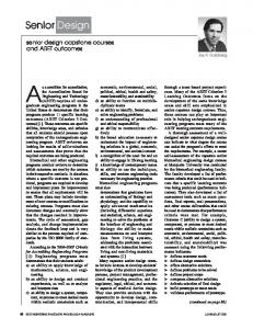
Fig. 1. Evolution of the dimensions of some relevant tokamaks compared with ITER and DEMO.
THE EU-DEMO MAIN REFERENCE: THE ITER PROJECT
The EU-DEMO design and development are expected to largely benefit from the experience gained through the ITER (International Tokamak Experimental Reactor) project. Fig. 1 compares the Vacuum Vessel (VV) and the plasma contour dimensions of some existing machines with ITER and EUDEMO. After a long preliminary design phase, ITER is under construction since 2006 in Cadarache (France). In 2010 ITER obtained the construction license for a basic nuclear installation, according to the French Nuclear Law. Presently, some ITER buildings, as well as several systems and components are under construction or already on site, while the design of other systems and components is under finalization with frequent R&D support, when not available on the market. ITER will show the scientific and engineering feasibility of plasma phenomena (such as confinement, burn, steady-state, disruption control and edge control) and plasma support systems (as low temperature superconducting magnets, fueling, heat & current drive systems). However, most of the components placed inside the ITER VV are not DEMO relevant because of the very different nuclear environment. Moreover, since ITER is an experimental machine, it is not connected to the grid to deliver electrical energy. Therefore, several outstanding technologies and physics integration issues need to be faced for DEMO, including the Breeding Blanket (BB) concept with the selection of the blanket coolant, the Divertor (Div) concept, the heating and current drive (H&CD) mix, a compatible plasma scenario and its duration, the BoP, and the remote maintenance schemes.
Fig. 2. Simplified block diagram of the DEMO power plant.
III.
GENERAL LAYOUT OF THE DEMO PLANT
Several systems are necessary in order to produce and control the plasma, to convert the fusion power into electrical power to be delivered to the grid and to ensure safety and plant protection. Fig. 2 sketches the main DEMO systems and the relevant interfaces, while a preliminary layout of DEMO buildings and areas is reported in Fig. 3.
Fig. 3. Preliminary layout of the DEMO plant.
IV.
THE DEMO NUCLEAR ISLAND
The Nuclear Island (NI) includes the Tokamak Building (11), the Tritium Building (14), the Active Maintenance Facility (21), the Hot Cell (HC) and the Radwaste Building (23). A. The Tokamak Building The Tokamak Building hosts the tokamak itself and all the systems or their terminal part necessary to create, control and monitor the plasma, including the protection and mitigation systems for safety and plant protection, as well as the system for the removal of the plasma power. The most demanding ones in terms of dimensions are: the VV, the magnet system (MS) and their terminals (feeders), the PHTS, the cryogenic distribution systems, the EPS, the Instrumentation and Control (I&C) cubicles, the auxiliary heating systems, particularly NBI, the vacuum system, the plasma diagnostics, the magnet energy fast discharge systems, and the VV pressure suppression systems. The VV and the toroidal field (TF) coil assembly are the two “backbone” structures of the tokamak, as they support the other components. The main systems of the tokamak structure (VV, MS, and Cryostat) are described in the following. B. The Vacuum Vessel • The VV is a torus-shaped double-walled pressure vessel. It provides the primary vacuum (at very low pressure and at very high purity in order to optimize the D-T fusion reaction) and shields the MS from neutrons. The VV supports the in-vessel components and other systems:
• The BB with First Wall (FW). The actively cooled FW withstands the plasma heat radiation and the additional heat loads due to impacting particles. The actively cooled breeder units contain lithium that is transmuted into tritium due to the neutron radiation. The tritium is removed from the breeder unit in a closed loop and extracted from that loop by the tritium extraction system. The heat from both FW and breeder unit is exhausted by the primary coolant and transferred to the secondary cooling loop via the heat exchanger. • The Div is primarily a high heat flux component. The magnetic topology is chosen in such a way that the field lines outside the last closed flux surface intersect the Div targets, collecting most of the particles and of the energy exhausted by the plasma. In the intended operation scenario, the Div target is subject to the highest heat loads; the particle impact causes the most severe erosion in the tokamak. C. The Magnet System The MS is an assembly of superconducting (SC) coils creating the magnetic field required to breakdown and confine the plasma, to drive its current, and to define its poloidal structure [3]. It is actively cooled by liquid He at about 4 K. Both the electric current and the liquid He are supplied by extokamak systems through feeders to the coils. The MS include the poloidal field (PF) and the Central Solenoid (CS) coils. Six PF coils are installed to the outboard leg of the TF coils and provide the vertical and radial magnetic field. Whereas the TF coil current is constant during the plasma operation, the currents in the PF coils change over the duration of the plasma pulse, contributing to drive the plasma current but also to actively stabilize the plasma itself.
The CS is a stack of coils in the borne of the torus. It is charged before plasma operation. Its current is then partly discharged providing the voltage required to break-down the H isotopes gas into a plasma. It is further discharged over the duration of the plasma pulse, driving the plasma current until it reaches the opposite peak current, which marks the end of the pulse. D. The Cryostat The Cryostat is a large, single-walled, passively cooled vacuum vessel at room temperature. It provides the vacuum required to operate the MS in cryogenic condition and supports the two backbone structures of the tokamak: the VV and the TF coil system. It is itself supported by the tokamak building. E. Other Systems and Buildings Several other systems are necessary to produce and maintain the fusion reactions: • Auxiliary heating systems, Electron Cyclotron Heating (ECH) and Ion Cyclotron Heating (ICH), whose front parts (launchers/antennas or ducts/liners) are integrated in the assembly of blanket segments and Neutral Beam Injection (NBI). These systems face the plasma and radiate electromagnetic waves (ECH and ICH) and neutrons (NBI) into the plasma, transferring energy and providing also additional functions as the support of plasma breakdown, heating, control, and current drive. The electromagnetic waves are generated outside the tokamak building and delivered to the plasma through waveguides. • Diagnostics. There is variety of different sensors that are installed on the vessel, on the in-vessel components, or in VV port structures. They measure the plasma and the magnetic field parameters, mostly in the framework of the plasma control system. • Fueling system. It is located outside tokamak, forms pellets of frozen D, T, or D-T, accelerates these pellets, and guides them through a pipe up to the level of the FW. The pipe runs through a vessel port and penetrates the in-vessel components. Alternatively, a gas fueling system could be considered. • The Tritium Building (14) is devoted to the fuel cycle, reprocessing part of the tritium recovered from the VV in order to maintain the adequate purity and also the composition of the fuel (D2-T2). • The Active Maintenance Facility is a huge area devoted to the remote handling of the in-vessel components (as the Div and the BB). They need to be replaced time to time because their qualified life is shorter than the plant life due to the damages induced by the fusion highenergy neutrons. • The Hot Cell is devoted to the conditioning of the activated material, e.g. the component detritiation, as activated components are not accepted in the radwaste permanent repository if they contain significant quantity of tritium.
F. Nuclear Confinement Barriers The VV, where the fusion reaction takes place, contains significant radioactive inventories and energies that could mobilise them in case of an accident. Therefore, the VV and its extensions, up to the isolation barriers, constitute the first fundamental confinement system. The Tokamak Building constitutes the secondary and ultimate confinement barrier against the possible losses of radioactive material after an accident that is not fully contained in the VV. The Tritium, the Active Maintenance Facility, the Hot Cell, and the radwaste buildings stand as the secondary confinement of the radioactive material contained inside the process or Remote Handling (RH) systems. V. DEMO SAFEGUARD SYSTEMS These systems perform the safety functions located outside the NI, as they do not contain radioactive sources. They provide safety functions for auxiliaries, which is redundant and qualified for all design basis events. Among them it is worth recalling the electrical power (Emergency Diesel Generators and Batteries and the relevant Emergency Electrical Systems, buildings 44, 45, 47, 49), the Emergency Compressed Air and other auxiliary safety fluids (e.g. demineralised water), the safety qualified Component Cooling Water Systems (CCWS), the Monitoring and Control Safety System, the main and backup Control Rooms, the Resistors of Toroidal Coil Quench Protection System (75) and the Access Control System (24). VI. THE DEMO BALANCE OF PLANT DEMO, and fusion plants in general, need a huge BoP, particularly a complex PCS where the secondary circuits of the various PHTS systems of the BB, Div and VV should be integrated into an industrial, reliable and efficient system. The primary loop, the Energy Storage System (ESS) if any, and the PCS will be localised in the Tokamak Building, in Building 77, and in Building 78, respectively. Another large and complex system is the electrical power supply serving the Tokamak that can be fundamentally assimilated to a large “electromagnetic machine”. The electrical Buildings are 17, 31, 32, 33, 36, 38 and are dedicated to the Magnets, NBI, and radiofrequency needs. The huge area including Buildings 77, 78, 81, 82 is dedicated to the electrical switchyard where DEMO will receive and deliver power to two 400-kV electrical lines and to the compensation of the huge reactive power required by inductive loads and bridge converters. In order to provide a measure of the dimensions of the electrical system, DEMO will require a recirculating electrical power in the range of 300-500 MW (about one order of magnitude bigger than the recirculating power of a conventional NPP). This huge value, together with that relevant to the pulsed operation, will require a site close to very well interconnected electrical nodes of the EU grid. Similarly, DEMO needs a vast cryoplant (Building 51), devoted to the production and distribution of the cryogenic fluids (as a reference, ITER needs about 21 ton of He at 4 K).
VII. THE COOLANT SYSTEMS While water is foreseen for cooling the Div and the VV, two options are currently considered for the coolant of the breeding blanket: He at 300-500°C and 80 bar; water at 295328 °C and 150 bar. Up to now the efforts have been focused on the BB cooling system as the power to be extracted represents 80% of the entire fusion power. Preliminary conceptual designs for both BB Helium Cooled Pebble Bed (HCPB) PHTS and BB Water Cooled Lithium Lead (WCLL) PHTS and relevant PCS have been developed [4]. The HCPB conceptual design foresees a highly degree of segmentation of the BB PHTS cooling loops that 3 and 6 for Inboard Blanket (IB) and Outboard Blanket (OB), respectively. Thanks to 9 Intermediate Heat Exchangers (IHXs), the BB PHTS delivers the thermal power extracted by He to an intermediate ESS that relies on molten salt as coolant. This intermediate system, in cascade, transfers the heat power to the PCS working fluid through 4 Helical Coil Steam Generators (HCSGs). The ESS also collects a certain amount of energy during the plasma burn phase to be used in the dwell time, in order to attenuate the potential negative effects that load variations between pulse and dwell times might have on BoP equipment (e.g. heat exchangers and turbines). The PCS adopts a conventional Rankine thermal cycle, which delivers superheated steam to the turbine at about 78 bar and 435 °C. In order to increase the overall plant efficiency, the heat recovered from Div and VV is used to heat-up the feedwater. Moreover, since the energy of Div and VV is not stored during the pulse period, in order to limit thermal transients due to the pulse/dwell cycling inside components as turbine and steam generators (SGs), the feed-water heat-up strategy foresees to warm up some segments of the PCS circuit in parallel by using some conventional feed-water heaters employing the steam extracted from turbine as heat source. The DEMO WCLL BB is connected with two separate PHTSs, which cool respectively the breeding zone and the FW. Both PHTSs present two cooling loops but the former is directly connected with the PCS by two Once Through Steam Generators (OTSGs), whereas the latter adopts two IHXs which link it with the ESS. During the plasma burn phase, the power of the breeding zone allows the OTSGs to produce slightly superheated steam, which feeds the turbine and realize a PWR-like Rankine cycle. Meanwhile, the FW power is transferred through the IHXs to the ESS that accumulates thermal energy, which is used during the dwell time to generate steam by means of four HCSGs. Even in the WCLL concept, the powers of Div and VV are used to heat-up the feed-water in parallel with other conventional feed-water heaters according to the strategy previously described for the HCPB concept. The following concerns and possible design optimization are under consideration for He cooling: • The large space required to integrate a large number of loops (9 loops, 3 for inboard blanket and 6 for outboard blanket) in the Tokamak Building that already includes many systems.
• The large pumping power requirements (100-150 MW), because of the pressure drops in the BB that are strongly design dependent. • The limited availability of large He circulators. • The large expansion volume (tens of thousands m3) in case of an in-vessel loss of coolant (LOCA). • The need of large size (>1 m) and long pipes (9 km) transporting high temperature He gas. • Coolant chronic leakages and tritium permeation particularly through steam generators might be issues to be considered at an early stage of the design. On the other hand, the following issues have been identified for the option with water cooling: • Production of radionuclides N16 and N17 due to interactions of high energy neutron with water and resulting radiation doses in areas where PHTS is localized. This requires shielding and accurate layout of the PHTS versus sensible equipment (e.g. I&C). • LiPb-water reaction and W dust-air or steam reaction. • Large volume of ESS. • Embrittlement of EUROFER at the water operating temperature. A preliminary design has been performed as well as the localization of the main systems and components in the tokamak building that has to accommodate many complex systems with sometime contrasting layout criteria. The possibility of a direct coupling of PHTS with PCS, with the elimination of the ESS is under analysis with support from nuclear Industry. The aim is to maintain the turbine at its nominal speed with the generator synchronized with the electrical grid, in order to provide the minimum steam to the turbine that is necessary to avoid thermal stresses and to maintain the nominal speed or together with a motorization of the generator during the dwell time. A recent reduction of the dwell time to the minimum possible (10 minutes), make this proposal interesting. Analyses that are more detailed are ongoing to assess the issues on other PCS components, like SGs or feedwater pre-heaters. VIII. THE ELECTRICAL POWER SUPPLY SYSTEM Fig. 4 shows a simplified scheme of the ITER EPS [5]. As in ITER, the network that will provide the power supply to the DEMO plant consists of two parts: 1. The Steady State Electrical Network (SSEN) supplies the power needed to operate the classical systems of the plant. The major consumers are the cooling and cryogenic systems requiring together about 80% of the total demand of about 120-250 MW for the water and He BB models respectively. 2. The Pulsed Power Electrical Network (PPEN) provides the large pulsed power needed to supply the superconducting coils and the H&CD systems.
Fig. 4. The ITER AC power systems: SSEN and PPEN [5].
The total peak active pulsed power demand is huge (in ITER it is 500 MW [5]). This includes the power required to operate and control the PF coils, the power needed for the positioning and the shape control of the plasma current, including the vertical stabilization, the power to charge the CS coils, and the power to supply the H&CD systems. Due to these power levels, partially necessary even during the dwell time, the DEMO plant should be located in a very well interconnected node of the EU electrical grid characterised by a high short-circuit power. A reactive power compensation system, among the world largest ever built so far, will make sure that the reactive power absorbed from the grid does not exceed the level imposed by the Electrical Transmission System Operator. Unlike ITER [5], the DEMO electrical scheme will include also an electrical generator that, besides of supplying the DEMO auxiliary systems, will deliver the produced energy to the grid. Fig. 5 shows the preliminary estimation of the DEMO power demand. The emergency diesel generators (D/G) have to be sized in order to face the electrical power required during the dominant accident sequences. The largest emergency electrical loads are the detritiation systems and the component cooling water systems. An early development of the DEMO EPS design, with a close interaction with the systems requiring the hugest electrical power also in terms of time derivative, is essential in order to maintain under control the dimension of the system (and of the relative building) and the interfaces with the electrical grid. The definition of a preliminary electrical load list characterised by the power requested versus time and the ITER experience are essential in order to define the EPS and to evaluate also the possibility of innovative solutions as the storage of energy on site in case of short duration of the pulsed loads. IX.
Fig. 5. DEMO preliminary power demand (He-cooled concept).
The pulsed operation of the plasma, the fast increase (and reduction) of the fusion power to be extracted by the cooling, the presence of different temperatures and of different fluids in some model of DEMO, ask for unconventional solutions for the cooling system design, if compared with a commercial NPP. An alternative solution to the ESS, whose presence increases the complexity of the plant, is under analysis with the support from Industry envisaging a direct coupling of the PHTS to PCS and adopting specific solutions to soften the transients on the turbine and on other components of the PCS. The complexity of DEMO in terms of amount of systems necessary to produce and control the plasma, the huge and often pulsed electrical power requested also during the dwell time, and the large reactive power to compensate ask for a huge and complex EPS. Any effort to reduce the complexity of DEMO through a simplification and a rationalization of the design and operation of the main systems are expected to have a beneficial return on the design of BoP systems (particularly PHTS, PCS, and EPS), on the safety and on the operation, availability of the plant and ultimately on the costs. REFERENCES [1]
[2]
[3]
CONCLUSION
The demonstration of the feasibility of electricity production before 2050 in an EU-DEMO that produces its own fuel represents the primary objective of the fusion development program in Europe. A brief description of the project is reported in this paper outlining the requirements and the open issues of the two main auxiliary systems: the cooling systems and the electrical power supply systems.
[4]
[5]
EFDA, Fusion Electricity – A roadmap to the realisation of fusion energy, November 2012. Online: http://users.eurofusion.org/iterphysicswiki/images/9/9b/EFDA_Fusion_Roadmap_2M8J BG_v1_0.pdf G. Federici et al., Overview of the design approach and prioritization of R&D activitiestowards an EU DEMO, Fus. Eng. Des. 109-111 (2016) 1464–1474. A. Lampasi, S. Minucci, “Survey of Electric Power Supplies Used in Nuclear Fusion Experiments,” 17th IEEE International Conference on Environment and Electrical Engineering (EEEIC), Milan, Italy, 6-9 June 2017. L. Barucca, S. Ciattaglia, M. Chantant, A. Del Nevo, W. Hering, “Status of EU DEMO Heat Transport and Power Conversion Systems,” ISFNT13, Kyoto, Japan, Sept. 2017. J. Hourtoule, et al., ITER electrical distribution system, IEEE 25th Symposium on Fusion Engineering (SOFE), San Francisco, CA, 2013, pp. 1-5.