Aug 25, 2014 - be determined based on the formulas (1) and (2) derived in [10], namely: (1) p .... [5] J. W. Pilarczyk, Analiza przyczyn zmian wÅasnoÅci drutów.
M. SULIGA, R. KRUZEL, T. GARSTKA, J. GAZDOWICZ
ISSN 0543-5846 METABK 54(1) 161-164 (2015) UDC – UDK 621.778:669.14.018:620.18:539.417=111
THE INFLUENCE OF DRAWING SPEED ON STRUCTURE CHANGES IN HIGH CARBON STEEL WIRES Received – Primljeno: 2014-03-26 Accepted – Prihvaćeno: 2014-08-25 Preliminary Note – Prethodno priopćenje
In the paper the influence of the drawing speed on structure changes has been assessed. The Scanning Electron Microscope investigation confirmed that for wires drawn with high total draft, exceeding 80 %, makes it impossible to clearly assess the impact of drawing technology on structural changes in the drawn wires. Thus, to assess the structural changes necessary to apply quantitative methods. On the basis of examination of the wire structure by measuring of electrical resistance, the structure changes in drawn wires has been determined. It has been shown that the increase of drawing speed, especially above 15 m/s, causes an increase in structure defect, with a decline in platelet orientation of cementite in drawn wires. Key words: wire, high carbon steel, drawing speed, structure, wire resistance
INTRODUCTION The intensification of the drawing process changes the deformation conditions forcing producers to use new technological solutions in the field of surface treatment, lubrication and drawing process [1]. The work of [2] shows that the application of high drawing speeds in the multipass drawing process of high carbon steel wires, on the order of 20 m/s, causes deterioration of lubrication condition, increased strength properties and a decline in plasticity and technological properties of the wire. From the available scientific literature also shows that drawing technology significantly affect microstructural changes during the drawing process of high carbon steel wires [3-5]. In work [6] has shown that the degree of deformation, elongation and orientation parallel to the drawing axis of the cementite plates is dependent on their orientation relative to the axis of the drawing. According to several authors [5, 7], ce-mentite plates arranged perpendicular to the axis of the wire to deform by bending and buckling, and in the case where these plates are arranged at angles to the axis of the desire of pregnancy, very rapidly and their fragmentation. In connection with the above, it is believed that the change in the drawing conditions in the high speed wire drawing process, reflected by an increase in non-uniformity of deformation and work hardening of the wires should adversely affect the orientation of cementite platelets and increase in the degree ferrite defects. Therefore, the present work makes an attempt to assess the influence of the drawing speed on structural changes in high carbon steel wires. M. Suliga, R. Kruzel, T. Garstka, Czestochowa University of Technology, Czestochowa, Poland J. Gazdowicz Institute of Ferrous Metallurgy Gliwice, Poland
METALURGIJA 54 (2015) 1, 161-164
MATERIAL AND APPLIED DRAWING TECHNOLOGIES The investigation of high speed multipass drawing process in conventional dies performed for high carbon steel wire grade C78D (0,79 % C). Before drawing, the wire rod was patented, itched and phosphated. The drawing process of 5,5 mm wires in the final wire of 1,7 mm was conducted in 12 passes, in industrial conditions, by means of a modern multi-die drawing machine Koch KGT 25/12, using conventional dies with an angle of drawing 2 = 12. The drawing speeds in the last pass, depending on the variant of the drawing, was respectively: 5, 10, 15, 20, 25 m/s.
THE EVOULATION OF STRUCTURE DURING WIRE DRAWING PROCESS Observations of structural changes in the drawing process of high-carbon steel wires was performed on scanning electron microscope Philips Inspect F. In Figure 1 show a typical high-carbon steel after patenting pearlitic structure of pearlite colonies developed in which there is a random distribution unoriented cementite plates of varying lengths and thicknesses. In the drawing process with an increase of the total draft gradual fragmentation of pearlite colony accompanied by the gradual laying of the cementite plates parallel to the axis of the wire. Thus, at work, in Figures 2 and 3 shows an example of the structure evolution. The analysis shows that in pearlitic steels at total draft including more than 60 % there is considerable fragmentation of the cementite. The exact determination of the degree of orientation and fragmentation cementite requires the analysis of a number of micro are161
M. SULIGA et al.: THE INFLUENCE OF DRAWING SPEED ON STRUCTURE CHANGES IN HIGH CARBON STEEL WIRES
as. At high magnification analysis area is relatively small relative to the total volume of the wire. Accordingly, without the use of quantitative methods for assessing fragmentation and orientation of cementite platelets as described in the work [6-8], and [5], it can be concluded only by the examined phenomena qualitatively. In contrast, there is no basis for the quantitative comparison of orientation of the cementite plates in the drawn wires.
EXAMINATION OF THE WIRE STRUCTURE BY MEASURING OF ELECTRICAL RESISTANCE
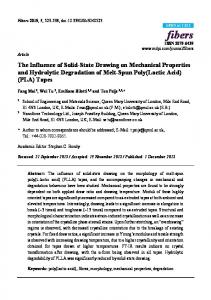
Figure 1 Pearlitic structure of φ 5,5 mm wire rod after patenting
Figure 2 Microstructure of φ 2,19 mm wire
The test in the previous section scanning showed that by drawing band structure is formed, and cementite platelets orientation, and degree of fragmentation depends mainly on the total draft, and partly on the drawing speed. These studies provide a qualitative rather than a quantitative image. Accurate quantitative analysis based on SEM requires a method of measuring the orientation of the cementite plates. In [5] showed that the test results obtained by this method are consistent with the results of research based on multi-step analysis of the orientation of the cementite plates, and the method of measuring the electrical resistance on the wires with a length of several hundred millimeters is an important complement to the qualitative observations obtained quantitative microscopic methods. Resistivity of the material depends on a number of factors, such as chemical composition, level of impurities, structure defects and its value is the sum of ideal and residual resistance [9-10]. Wherein the ideal resistance is due to the thermal vibration of atoms crystallographic lattice and is dependent on the temperature, and residual resistivity is independent of temperature, however, depends on the defect of steel crystal structure. To separate the resistance is used in the literature known Matthiessen rule, which permits evaluation of the effect of deformation on the structure of the one and two-phase metal [10]. According to the Friedel work [11] the resistance depends on the dislocation density and the packing of the cementite in the pearlite. The drawing process with an increase of the total draft defected structure increases, which causes increase in the residual resistance, whereas the ideal resistance trend is reversed. Namely, along with an increase in deformation increases orientation structure of pearlite grains initially randomly arranged to gradually change the axis direction of the drawing. When total draft in excess of 60 % is already heavily targeting the structure, while the fragmentation of the cementite plates. The examination of the wire structure by measuring of electrical resistance consists in measuring the resistance of the wire at two different temperatures, i.e. at ambient temperature and liquid nitrogen. The relative change in the ideal and the residual wire resistance can
Figure 3 Microstructure of φ 1,7 mm wire
162
METALURGIJA 54 (2015) 1, 161-164
M. SULIGA et al.: THE INFLUENCE OF DRAWING SPEED ON STRUCTURE CHANGES IN HIGH CARBON STEEL WIRES
be determined based on the formulas (1) and (2) derived in [10], namely: (1)
r
M z 1
M p
(2)
where: i
– relative change of the ideal resistance,
r
– relative change of the residual resistance, – relative change of the total resistance,
Mp
z
N2
Figure 4 The changes in the ideal residual resistance of drawn wires in drawing speed function
1, , Mz
Z N2
,
Z
– total resistance of the wire at ambient temperature, N 2 – total resistance of the wire in the liquid nitrogen temperature, z – resistance of the deformed wire at ambient temperature, Z N 2 – resistance of the deformed wire in the liquid nitrogen temperature. The relative change in the wire ideal resistance i / determine degree of orientation of cementite plates to the axis of the wire (the more negative the value, the greater orientation of the structure). While the relative change of the wire residual resistance r / determine the degree of structure defect (the more positive the value, the greater the defected and work hardening of material). Research orientation of cementite platelets and defects of the wire structure by electrical resistance measurement was carried out for the 1,7 mm final wires. The tested wires were placed inside the cryostat, that was filled of liquid nitrogen. By the separation of current and voltage electrodes, the influence of the wiring contact resistance was eliminated. The ends of the investigated wires were used as current terminals, wherein on one side, the endings were connected through conductive ring creating common electrode. As the current source the AX-3005D power supply with function of current stabilisation and integrated digital amperometer was used. During the experiments, constant current value I = 1A was maintained. The drop voltage U on each single wire by the pair of brass contacts was picked up and carrying to the voltage terminals. The distance l between the probe was 455 mm. Voltage was measured with high accuracy by the digital multimeter RIGOL DM3051. The measurements were repeated three times for each wire. Values of wires resistance R on the base of Ohm law were calculated, and then taking into consideration METALURGIJA 54 (2015) 1, 161-164
Figure 5 The changes in the residual resistance of drawn wires in drawing speed function
measuring length l and crosss sectional area of the wires, their resistivity ρ were determined. Similarly, in the same way, the resistivity of the wires was tested at ambient temperature. On the basis of equations (1) and (2), the relative change in orientation of the cementite plates i / and defected structure r / for 1,7 mm wires drawn in the speed range of 5-25 m/s has been estimated. The test results are shown in the figures 4 and 5 On the basis of Figure 4 and 5 it can be observed that the drawing speed has a significant impact on the value of the changes in the ideal and residual resistance of drawn wires, especially at drawing speeds in excess of 15 m/s It was found that an increase in the drawing speed of 5 to 25 m/s, causes the increase of the residual resistance of wires of about 4 %. Higher values of resistance changes r / in the wires drawn at high speeds indicate that at the same level of deformation increase in drawing speed increases the amount of material defects. Higher relative change value of the residual resistance r / for wires drawn at high speeds, may be provided not only an increase defects structure, but also the worse friction conditions, and may also suggest a greater disturbance of the structure orientation. The thesis of a worse packing of structure of wires drawn at high speeds confirm the higher values of relative chang163
M. SULIGA et al.: THE INFLUENCE OF DRAWING SPEED ON STRUCTURE CHANGES IN HIGH CARBON STEEL WIRES
es in wire resistance. Along with the increase in drawing speed decreases the orientation of cementite plates. Whereas, a significant increase in the relative ideal resistance in the wires drawn at high speeds should be seen in higher friction at the interface between the wire and the die, which resulted in greater inhibition of subsurface layers of the flow relative to the axis of wire. Hence the increase in drawing speed of 5 to 25 m/s resulted in a decrease of approximately 7 % cementite platelets orientation, as confirmed by higher values i / .
CONCLUSIONS From the experimental studies carried out, the following findings and conclusions have been drawn: Band structure in the wires drawn with high total draft, exceeding 80 %, makes it impossible to clearly assess the impact of drawing technology on structural changes in the drawn wires. Thus, to assess the structural changes necessary to apply quantitative methods. The method of measuring the wires resistivity allows to determine the influence of drawing speed on structural changes in the drawn wires. The increase of drawing speed, especially above 15 m/s, causes an increase in structure defect, with a decline in platelet orientation of cementite. This is due to the deterioration of lubrication conditions at the interface between the wire and die.
REFERENCES [1]
[2]
M. Suliga, The influence of the high drawing speed on mechanical-technological properties of high carbon steel wires, Archieves of Metallurgy and Materials, (2011) 3, 823-828. [3] E. A. D. Aernoudt, Drawing induced structural and mechanical anisotropy, Mordica Memorial Lecture, WAI’s 79th Annual Convention, 27 April, 2009. [4] S. K. Lee, D. C. Ko, B. M. Kim, Pass Schedule of wire drawing process to prevent delamination for high strength steel cord wire, Materials and Design, 30 (2009), 29192927. [5] J. W. Pilarczyk, Analiza przyczyn zmian własności drutów ciągnionych konwent-cjonalnie i w ciągadłach ciśnieniowych. Seria Monografie No 39, Politechnika Częstochowska, Częstochowa 1996. [6] G. Langford, A study of the deformation of patented steel wire, Metallurgical Transactions, 2 (1970), 465-477. [7] G. Langford, Deformation of pearlite. Metallurgical Transactions A, 8 (1977) 6, 861-875. [8] A. Walentek, Quantitative characterization of microstructure of two phase materials: the case of pearlite. Katholieke Universiteit Leuven, Leuven 2007 (Doctoral thesis). [9] R. Fougeres, M. Theolier: Mechanical and physical properties of high – carbon steel wire work – hardened by drawing. Revue de Metallurgia, 67 (1970) 2, 100-112. [10] J. W. Pilarczyk, Zastosowanie pomiarów oporu elektrycznego drutów ze stali węglowych do oceny zmian strukturalnych, wprowadzanych procesem ciągnienia. Hutnik – Wiadomości Hutnicze, (1986) 1, 19-24. [11] U. Friedek, Dislocations Edison Vesley, Amsterdam, 1964. Note: The professional translator for English language is Krzysztof Skorupa, Myszków, Poland
M. Suliga, Analysis of the multipass steel wire drawing with high speed in conventional and hydrodynamic dies (in Polish), monograph No. 32, Czestochowa University of Technology: Czestochowa 2013.
164
METALURGIJA 54 (2015) 1, 161-164