10
IEEE TRANSACTIONS ON MICROWAVE THEORY AND TECHNIQUES, VOL. 57, NO. 1, JANUARY 2009
Third-Order Intermodulation Distortion and Harmonic Generation in Mismatched Weakly Nonlinear Transmission Lines Jordi Mateu, Member, IEEE, Carlos Collado, Member, IEEE, Nathan Orloff, James C. Booth, Eduard Rocas, Student Member, IEEE, Alberto Padilla, and Juan M. O’Callaghan, Senior Member, IEEE
Abstract—This paper describes a procedure to obtain analytical expressions for the spurious signals generated in nonlinear transmission lines with impedance mismatch when they are subject to small-signals. Using these expressions one can rapidly extract the nonlinear parameters describing the nonlinear effects due to the conductor, ( ) and ( ), such as in superconductors, and/or the nonlinear parameters due to the dielectric, ( ) and ( ), such as in ferroelectrics. The resulting closed-form expressions have been validated by equivalent circuit simulations. Spurious signal measurements on several coplanar waveguide superconducting and ferroelectric transmission lines have been explained by the use of the resulting closed-form expressions. Index Terms—Ferroelectrics, harmonic balance, intermodulation products, nonlinear measurements, nonlinearities, superconductors.
I. INTRODUCTION ROADBAND response of materials to electromagnetic stimuli provides important information about their electronic and fundamental properties. This information may help to accelerate the development and incorporation of new electronic materials such as high-temperature superconductors (HTSs), ferroelectrics, and magneto-electric and/or multiferroics in general, into devices used for electronic applications [1]–[3]. For such characterization, we have used broadband coplanar waveguide (CPW) structures [2]. We have extracted the electrical parameters for the broadband frequency response of our CPW structures using accurate calibration techniques [4]–[6]; these electrical parameters may then be related to
B
Manuscript received June 17, 2008; revised October 14, 2008. First published December 16, 2008; current version published January 08, 2009. This work was supported by the Spanish Ministry of Science and Technology and the Spanish Government (CICYT) under Grant MAT-2005-05656-C03/C04 and Grant TEC-2006-13248-C04-02/TCM and Contract RYC-2005-001125 and Contract BES-2007-16775. This work was supported in part by the U.S. Government. J. Mateu, C. Collado, E. Rocas, A. Padilla, and J. M. O’Callaghan are with the Department of Signal Theory and Communications, Universitat Politècnica de Catalunya (UPC) and Centre Technologic de Telecomunicacions de Catalunya (CTTC), Barcelona 08034, Spain (e-mail:
[email protected];
[email protected];
[email protected];
[email protected];
[email protected]). N. Orloff and J. C. Booth are with the National Institute of Standards and Technology, Boulder, CO 80305 USA (e-mail:
[email protected];
[email protected]). Color versions of one or more of the figures in this paper are available online at http://ieeexplore.ieee.org. Digital Object Identifier 10.1109/TMTT.2008.2009083
the properties of the constituent materials. Recently, these techniques have been used to characterize fluids embedded in microchannel structures integrated with CPW test structures [7], [8]. While this broadband linear characterization is a necessary step toward the complete understanding of the electromagnetic response of these different materials, it does not always yield sufficient information to distinguish between different theoretical models, and therefore, may not provide a complete understanding of the material properties. Additional information can be obtained for such materials from the third-order nonlinear response to electromagnetic stimuli [9]–[12] such as intermodulation distortion products or third-order harmonics. These types of spurious signals are often detectable at low signal levels, when there are no measurable effects on the fundamental response of the system (i.e., that occurring at the frequencies of the driving stimuli). For example, third-order intermodulation products are often measureable when no compression effects are seen in a two-port device, or when no de-tuning is observed in a resonator [13]. To obtain the nonlinear response of different materials we have developed a broadband two-tone high-dynamic-range measurement system to capture the spurious signals resulting from the nonlinear transmission lines [11], when they are fed with weak fundamental tones. Accurate circuit models that relate the measured spurious signals to the nonlinear circuit parameters are then essential to characterize the nonlinear properties of the materials using parameters that are independent of the specific test devices used in the measurements. Both commercial and custom simulation software have been used to adjust the relevant parameters in these equivalent circuit models so that their response fits the measured results [11]. In this study, we analyze these circuit models to obtain an analytical closed-form expression of the spurious signals generated in a mismatched nonlinear transmission line (MNLTL) as a function of the nonlinear distributed circuit parameters, which, in turn, may be linked to the nonlinear material properties [9], [11]. Note that these expressions are only valid in a small-signal regime, i.e., when no effects on the fundamental response are observed. The circuit model for an MNLTL is described in Section II, and the analytical procedure to obtain closed-form expressions is presented in Section III and supported by the formulation of the Appendix. Due to the effect of mismatch, these expressions need to account for the presence of standing waves of the spurious signals on the transmission lines. The complexity of the
0018-9480/$25.00 © 2008 IEEE Authorized licensed use limited to: IEEE Xplore Customer. Downloaded on February 4, 2009 at 07:31 from IEEE Xplore. Restrictions apply.
MATEU et al.: THIRD-ORDER INTERMODULATION DISTORTION AND HARMONIC GENERATION
11
Fig. 2. Equivalent-circuit model of an elemental segment of length dz of a nonlinear transmission line.
0
0
Fig. 1. Third-order nonlinear signals (at frequencies 2f f , 2f f , 3f , 2f + f , 2f + f , and 3f ) generated by a two-tone incident signal with fundamentals f and f .
analysis requires verification of the resulting closed-form expression with simulated results. Section IV compares the spurious signals generated in an MNLTL using both the circuit simulation and the closed-form expressions. Finally, in Section V, we used the obtained closed-form expression to fit the spurious signals measured in an MNLTL [11]. II. NONLINEAR RESPONSE AND CIRCUIT MODEL FOR MNLTL When a broadband nonlinear transmission line is fed with two weak tones, at frequencies and , spurious signals appear at mixing products and harmonics of the two fundamental driving tones. Typically for third-order nonlinear products, we observe spurious signals at the intermodulation products at frequencies and , the interclose to fundamental tones and , modulation products at high frequencies and (see as well as the third harmonics at frequencies Fig. 1). Understanding the relationships between the different spurious signals generated by the nonlinear effects in the material (conductor or dielectric) is very important in order to find an accurate circuit model to describe their small-signal nonlinear response. Note that due to the distributed nature of the nonlinear effects, additional spurious signals would appear at other mixing frequencies. However, since we operate a small-signal regime, they may be usually neglected. In the case of a unified description of the different spurious signals resulting from a perfectly matched nonlinear transmission line, one would expect a simple relationship between the spurious signals. In this case, due to the distributed nature of the nonlinear effects, the spurious signals show a characteristic linear dependence on the transmission line length. Closed-form expressions for this case were reported in [9] and [14]. However, when we characterize dielectric materials with high permittivity or a priori unknown permittivity, our CPW test structures usually result in mismatched transmission lines. In this case, the relationship between the spurious signals generated is not as straightforward and effects that one expects, such as length dependence due to the distributed origin of the nonlinear properties, might not be directly identified from the measured results. A. Circuit Simulation As we have done in our previous studies [9], [11], [14], we used a circuit simulator to extract the circuit parameters characterizing the nonlinear transmission line response. To accomplish this, we modeled the nonlinear transmission line by cascading
many nonlinear elemental cells together, such as the one and correspond to shown in Fig. 2. The circuit parameters the resistance and inductance per unit length, respectively, and in a quasi-TEM transmission line may be related to the mateand are the conductance rial properties of the conductor. and capacitance per unit length, respectively, and may also be linked to the dielectric properties. The nonlinear properties of the material (conductor or dielectric) may also be accounted for in the equivalent circuit of Fig. 2. To do that, we may use the curve and the characteristic curve (the characteristic flux being ) to define the distributed resistance and inductance as a Taylor series expansion (1) (2) Similarly we use the characteristic curve and the characcurve ( being the charge) to define the distributed teristic conductance and capacitance as a Taylor series expansion as (3) (4) The general nonlinear telegrapher’s equations may be written as
(5) Therefore, the nonlinear effects of the conductors are defined by a nonlinear inductance and a nonlinear resistance ( and ) that depend on the total current flowing through the line, whereas the nonlinear effects due to the dielectric parts of the circuit are defined by a nonlinear capacitance and a nonlinear conductance and ( ) that depend on the voltage on the line. Note that this analogous approach is also used in [15] to obtain the second harmonic generated in a nonlinear transmission line. In [16], a similar small-signal approximation is used to assess the nonlinear effects in left-handed transmission lines. While the analysis using circuit simulations gives very accurate results, this approach requires significant amounts of computing time. In [9], we state that one requires cascading approximately 200 elemental cells per wavelength to get accurate results. This rapidly ramps up to few thousand cells for long lines, which, in turn, results in the same amount of nonlinear ports to be solved with harmonic balance algorithms. Moreover, this approach gives no insight into how the relevant parameters interact
Authorized licensed use limited to: IEEE Xplore Customer. Downloaded on February 4, 2009 at 07:31 from IEEE Xplore. Restrictions apply.
12
IEEE TRANSACTIONS ON MICROWAVE THEORY AND TECHNIQUES, VOL. 57, NO. 1, JANUARY 2009
with each other to generate the measurable quantities. Therefore, iterative steps are required to extract the nonlinear terms from measurements of the spurious signals [11].
Assuming that the propagation equation (10) accepts a solution of the form (15)
III. FORMULATION This section uses the equivalent circuit of an elemental segment of a nonlinear transmission line (Fig. 2) to obtain closed-form expressions for the third-order intermodulation , products—spurious signals appearing at frequencies , , and —and third harmonics—spuand —occurring in an rious signals appearing at MNLTL. This procedure starts by applying the nonlinear telegraphers’ equations, resulting from the set of equations (1)–(5) (6) (7)
where and are, respectively, the forward and backward waveform along the transmission line at , we obtain the following equation:
(16) and are the nonlinear sources at , where and should detailed in the Appendix. The resulting moreover satisfy the boundary conditions at both ends of the and , transmission line
where the terms and account for the nonlinear contributions due to the conductive and the dielectric parts, respectively. According to the equivalent circuit of Fig. 2, these terms can be written as (8) (9)
(17) (18) where
and are the reflection coefficients at the source and at the load at . To solve (16), we split the term on the right of (16) into its forward and backward components as
The propagation equation, for a given frequency component , resulting from the combination of (6) and (7), is
(19)
(10)
where and represent the forward and backward components. Using (19), we can rewrite (16) as
are, respectively, the propagation constant where and and characteristic impedance of the line at . and current terms act as The voltage nonlinear generators at , and they may be obtained by using the Fourier transform as (11) (12) where and are, respectively, the current and voltage at funand . damental frequencies Now using the current and voltage distribution along the line of (32) and (33), derived in the Appendix, and assuming a quadratic nonlinear dependence as and and
(13) (14)
(20) (21) Now we only need to solve the two ordinary differential equations (20) and (21), use the boundary conditions (17) and (18), and apply (15) to obtain the current distribution along the transat . mission line A. Intermodulation Product at This section uses the analytical procedure described above to obtain the current distribution along the line for the intermodu, . The forward lation product at and backward components are, respectively, detailed in (36) and (37). and are The resulting
where , , , and set the strength of the nonlinear effects, we analytically obtain the nonlinear voltage (11) and current (12) generators at the frequency components where the spurious signals occur. Note also that the assumption of quadratic nonlinear effects is consistent with many experiments reported in the literature [9]–[14]. Authorized licensed use limited to: IEEE Xplore Customer. Downloaded on February 4, 2009 at 07:31 from IEEE Xplore. Restrictions apply.
(22)
MATEU et al.: THIRD-ORDER INTERMODULATION DISTORTION AND HARMONIC GENERATION
13
(23) and are found applying the where the constants , , boundary conditions (17) and (18). The constants , , , and are related to the nonlinear terms and and are detailed in (38). Note that, throughout this paper, subscripts and indicate the frequency components at , , and , respectively. The development for the intermodulation product at would read as (22) and (23) by only replacing the components at by the ones at , and vice versa, and using the components at instead of at (this is using the subscript instead of ). B. Intermodulation Product at For the intermodulation product at and backward ward (40), respectively. The resulting are
, we use the forcomponents (39) and and
Fig. 3. Current at the end of the line for the spurious frequency components.
. where the subscript refers to the frequency components at are detailed in (48). Note that The constants , , , and these expressions would also be suitable for the third harmonic of . In the case of perfectly matched transmission lines, , the above closed-form expression would read as reported in [14]. IV. VERIFICATION: CIRCUIT SIMULATIONS
(24)
(25) Now the subscript refers to the frequency components at . The constants , , , , , and are detailed in (43). Again the result would be easily expanded for the spurious . signals occurring at C. Harmonic Generation at The forward and backward components of the current distribution along the line at are found using the forward and backward components of (46) and (47), respectively. and are The resulting (26) (27)
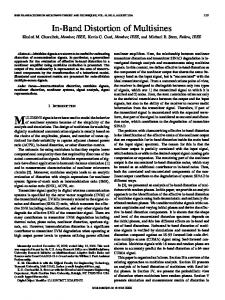
This section checks the expressions developed above in (22)–(28) by comparing their results with the ones obtained from a circuit simulation of an MNLTL. The circuit simulation has been performed as outlined in Section II-A, and reported elsewhere [9], [11]. The linear distributed circuit parameters defining the nH/m, simulated transmission line are pF/m, m, and S/m (almost lossless dielectric). This results in a transmission line of 36.7- characteristic impedance, which is then connected to a 50- source and terminated with a 50- load. For this simulation, we consider quadratic nonlinear effects coming from the conductor [see (13)], where and H/mA . We then feed this line with GHz and GHz and evaluate the two tones at , , , resulting spurious signals at , , and using the corresponding closed-form expressions and the simulated results. as a Fig. 3 depicts the current at the end of the line function of its length, for all spurious signals occurring in the nonlinear transmission line. The labels on the figure IMD-HF, IMD-LF, and 3H refer to the intermodulation distortion at and ), the intermodulation high frequency and ) and distortion at lower frequency ( the third harmonics, respectively. The circles indicate the simulated results at the lower sideband of the spurious signals, i.e., , , and , whereas the squares indicate the simulated results at the upper sideband of the spurious signals, , , and . The solid and dashed lines i.e.,
Authorized licensed use limited to: IEEE Xplore Customer. Downloaded on February 4, 2009 at 07:31 from IEEE Xplore. Restrictions apply.
14
IEEE TRANSACTIONS ON MICROWAVE THEORY AND TECHNIQUES, VOL. 57, NO. 1, JANUARY 2009
Fig. 4. Current at the end of the line for all spurious frequency components when the fundamental tones f and f are set to 3 and 3.5 GHz, respectively. ! , 2! + ! , and 3! , and dashed lines Solid lines correspond to 2! ! , 2! + ! , and 3! . correspond to 2!
0
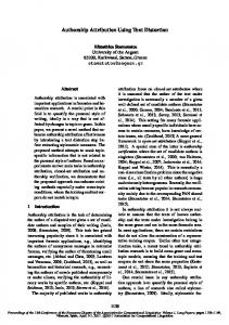
Fig. 5. Measurements and analytical results of the spurious signals occurring in a set of ferroelectric nonlinear transmission lines.
0
correspond to the values evaluated by the use of the closed-form expressions, all agreeing very well with the simulated results. The expected linear transmission line length dependence of the spurious signals can be used to confirm the distributed origin of the nonlinear effects and, therefore, rule out contributions from possible external nonlinear sources. Although the results in Fig. 3 show an increment of the spurious signals as a function of the length, they do not follow a linear dependence, as it occurs in a perfectly matched transmission line. The fluctuating length dependence, due to the mismatched effects, may give higher nonlinear effects in shorter lines. This makes it difficult to predict, from the raw data, the distributed origin of the nonlinearities without using simulations or the closed-form expressions developed here. Since the fluctuating behavior comes from the mismatched effects, it depends on the operating frequency and is, therefore, different for each spurious signal. This phenomenon, if not taken into account, may lead to misleading conclusions, such as asymmetries on the IMD (i.e., differences and ) due to between the signal power at memory effects [17]. Although not reported in this section, the closed-form expressions have also been verified when the nonlinear effects come only from the dielectric part and from both conductor and dielectric parts. We have also verified the obtained expressions for a several values of characteristic impedance ranging from 10 to 100 and different frequencies. As an example, to emphasize the effects of mismatch, this section also evaluates the length dependence of the spurious signals for lines longer than those of Fig. 3 (up to 0.2 m) fed with two input tones whose frequencies ( and ) are 3 and 3.5 GHz, respectively, much farther apart than those of Fig. 3. Fig. 4 shows how the asymmetries between the spurious signals are more pronounced. Moreover, unlike in Fig. 3, the IMD-LF traces in Fig. 4 have fluctuations for only limited ranges of length. From Figs. 3 and 4, we also see that small deviation in the length determination of the line may incur in a few decibel difference of the predicted spurious signal.
V. VERIFICATION: MEASUREMENTS Simulations using the circuit model of Fig. 2 have been extensively used to analyze the distributed nonlinear effects in superconducting transmission line, confirming the expected length and frequency dependence [18]. Since in superconducting transmission lines the dielectric constants of the substrates are usually well known, one can build transmission lines with characteristic impedances matched to 50 . For this case, we do not expect to observe any fluctuating effect due to the length of the line. The closed-form expressions developed here have also been used to explain such results. However, this is not the case for substrates with large or nonlinear dielectric constants, such as ferroelectrics [2] or magnetoelectrics [3]. Fabrication of transmission lines incorporating these materials then results in a nonlinear mismatched transmission line. This section applies the developed closed-form expressions to explain the nonlinear behavior occurring in CPW transmission lines incorporating an SrTiO (STO) thin film of 400-nm thickness grown on a LaAlO substrate with conductors defined by a 0.3- m Au layer on top. Here we report the intercept point at 0-dBm input power of the spurious signals occurring in four CPW transmission lines, all with a 50- m width of center conductor and 20- m gap between the center conductor and ground planes. The four lines have different length: mm, mm, mm, and mm. Fig. 5 shows the measured intercept point at 0-dBm input power and outlines the length dependence predicted from the closed-form expression developed here. Circles and squares indicate the measured intercept points of the spurious signal at and , respectively. The input tones and were set to 6 and 6.1 GHz, respectively. Experiments performed to obtain measurements of the spurious signals are detailed in [11]. We then used the current at the end of the line, obtained from (22)–(28), to extract the power at the output port [19]. The output power generated at spurious frequencies depends on the of the propagation constant and characteristic impedance line—obtained from a multiline thru-reflect line (TRL) calibration [4] as at each frequency point—and the nonlinear terms and , which are unknown. By equating the resulting output
Authorized licensed use limited to: IEEE Xplore Customer. Downloaded on February 4, 2009 at 07:31 from IEEE Xplore. Restrictions apply.
MATEU et al.: THIRD-ORDER INTERMODULATION DISTORTION AND HARMONIC GENERATION
15
indicates the current driven by the source and is the reflection coefficient to the source and load both at . The input may be found as impedance Fig. 6. Outline of a mismatched transmission line.
(29)
power expressions with the measured spurious signals, one can and . Note that, in this exextract the nonlinear terms ample, where all nonlinear effects are due to the dielectric part, . This the nonlinear effects from the conductor part are same procedure has been used in previous studies [9], [11], but the extraction of the nonlinear terms was carried out by iterating circuit simulations to match measured and simulated spurious signals. Fig. 5 reproduces the fitting of the experimental results reported in [11]. Dashed–dotted and dashed lines show the length dependence obtained from the closed-form expressions. Fig. 5 shows very good agreement between measurements and the length dependence obtained from the closed-form expressions.
The propagation constant and the characteristic impedance of the transmission line , respectively, can be obtained , , , and from the linear distributed circuit parameters of the line, as
(30) (31)
From the expressions above, i.e., (28)–(31), the current and voltage distribution along the line at fundamental frequency , or , are being
VI. CONCLUSION This study has developed general closed-form expressions to obtain the spurious signals resulting from a weakly nonlinear mismatched transmission line with quadratic nonlinear effects in both the conductor and dielectric parts of the circuit. The resulting closed-form expressions have been verified with circuit simulations. Assessment of the transmission line length dependence of the spurious signals reveals how the mismatch effect may mask the expected length dependence caused by distributed nonlinear effects. Without an accurate circuit model and extensive simulations, or without the use of the closed-form expressions developed here, nonlinear measurements may give misleading results due to the fluctuating length dependence and the asymmetry between spurious signals. Moreover, since the closed-form expressions show the interaction of the different sources of nonlinear effects, they offer the possibility of evaluating the nonlinear response and identifying the origin of the nonlinear effects in order to discern between different sources.
(32) (33) NONLINEAR VOLTAGE AND NONLINEAR CURRENT GENERATORS Assuming a quadratic nonlinear dependence of the distributed circuit parameters , , , and , as outlined in (13) and (14), we found the resulting nonlinear sources at the mixing products and harmonics of the fundamental comand by applying (13) and (14) into (11) and ponents at (12), respectively. Although this Appendix only details the non, , and linear voltage and current generators at , their counterparts at , , and , respectively, could be directly derived. The nonlinear voltage and the nonlinear current generators, are respectively, at
APPENDIX CURRENT AND VOLTAGE DISTRIBUTION AT FUNDAMENTAL FREQUENCIES In a transmission line for which the characteristic impedance is neither matched to the impedance of the source, nor the load (see Fig. 6), the current and voltage distribution along the line of the fundamental signals is obtained from basic theory of circuit analysis [19]. We start by obtaining the forward current component at the , , at ( for the fundamental cominput of the line ponents might by 1 or 2) as
(34)
(28)
(35)
Authorized licensed use limited to: IEEE Xplore Customer. Downloaded on February 4, 2009 at 07:31 from IEEE Xplore. Restrictions apply.
16
IEEE TRANSACTIONS ON MICROWAVE THEORY AND TECHNIQUES, VOL. 57, NO. 1, JANUARY 2009
where
and . Substituting (34) and (35) into (19), we may isolate the forward and backward components
where
(36)
(37) where (43) with
and . , the nonlinear voltage and cur-
For the third harmonic at rent generators are
(44) (38)
with
(45) and . where The forward and backward components then result as follows:
and
. By the used of analogous expressions to (34)–(38), the intermay be written as modulation products at
(46) (47) where
(39)
(48) (40) where now
and . The forward and backward components are
(41)
(42)
with
and
.
REFERENCES [1] D. E. Oates, P. P. Nguyen, G. Dresselhaus, M. S. Dresselhaus, G. Koren, and E. Polturak, “Nonlinear surface impedance of YBCO thin films: Measurements, modelling and effects in devices,” J. Superconduct. Novel Magn., vol. 8, no. 6, pp. 725–733, 1995. [2] M. J. Lancaster, J. Powell, and A. Porch, “Thin-film ferroelectric microwave devices,” Superconduct. Sci. Technol., vol. 11, pp. 1323–1334, 1998. [3] N. Orloff, J. Mateu, M. Murakami, I. Takeuchi, and J. C. Booth, “Broadband characterization of multilayer dielectric thin-films,” in IEEE MTT-S Int. Microw. Symp. Dig., 2007, pp. 1177–1180.
Authorized licensed use limited to: IEEE Xplore Customer. Downloaded on February 4, 2009 at 07:31 from IEEE Xplore. Restrictions apply.
MATEU et al.: THIRD-ORDER INTERMODULATION DISTORTION AND HARMONIC GENERATION
[4] R. B. Marks, “A multiline method for network analyzer calibration,” IEEE Trans. Microw. Theory Tech., vol. 39, no. 7, pp. 1205–1215, Jul. 1991. [5] D. F. Williams and R. B. Marks, “Transmission line capacitance measurements,” IEEE Microw. Guided Wave Lett., vol. 1, no. 9, pp. 243–245, Sep. 1991. [6] D. F. Williams and R. B. Marks, “Characteristic impedance determination using propagation constant measurements,” IEEE Microw. Guided Wave Lett., vol. 1, no. 6, pp. 141–143, Jun. 1991. [7] J. C. Booth, J. Mateu, M. Janezic, J. Baker-Jarvis, and J. A. Beall, “Broadband permittivity measurement of liquid and biological samples using microfluidic channels,” in IEEE MTT-S Int. Microw. Symp. Dig., 2006 , pp. 1750–1753. [8] J. Mateu, N. Orloff, M. Renihart, and J. C. Booth, “Broadband permittivity of liquids extracted from transmission line measurements of microfluidic channels,” in IEEE MTT-S Int. Microw. Symp. Dig., 2007, pp. 523–526. [9] C. Collado, J. Mateu, and J. M. O’Callaghan, “Analysis and simulation of the effects of distributed nonlinearities in microwave superconducting devices,” IEEE Trans. Appl. Superconduct., vol. 15, no. 1, pp. 26–39, Mar. 2005. [10] J. R. Ott, P. Lahl, and R. Wördenweber, “Nonlinear microwave properties of ferroelectric thin films,” Appl. Phys. Lett., vol. 84, no. 21, pp. 4147–4149, 2004. [11] J. Mateu, J. C. Booth, and S. A. Schima, “Frequency tuning and spurious signal generation at microwave frequencies in ferroelectric SrTiO thin-film transmission lines,” IEEE Trans. Microw. Theory Tech., vol. 55, no. 2, pp. 391–396, Feb. 2007. [12] R. Hammond, E. Soares, B. Willemsen, T. Dahm, D. Scalapino, and and intermodulation of low J. Schrieffer, “Intrinsic limits on the power high temperature superconducting microstrip resonators,” J. Appl. Phys., vol. 84, no. 10, pp. 5662–5667, 1998. [13] D. E. Oates, “Microwave superconductivity,” in Nonlinear Behaviour of Superconducting Devices, ser. NATO Sci. E: Appl. Sci.. Brussels, Belgium: NATO, vol. 375, ch. 5. [14] D. Seron, C. Collado, J. Mateu, and J. M. O’Callaghan, “Analysis and simlation of distributed nonlinearities in ferroelectrics and superconductors for microwave applications,” IEEE Trans. Microw. Theory Tech., vol. 54, no. 3, pp. 1154–1160, Mar. 2006. [15] K. S. Champlin and D. R. Singh, “Small-signal second-harmonic generation by a nonlinear transmission line,” IEEE Trans. Microw. Theory Tech., vol. MTT-34, no. 3, pp. 351–353, Mar. 1986. [16] A. B. Kozyrev and D. W. van der Weide, “Nonlinear wave propagation phenomena in left-handed transmission-line media,” IEEE Trans. Microw. Theory Tech., vol. 53, no. 1, pp. 238–245, Jan. 2005. [17] J. C. Pedro and N. B. Carvalho, Intermodulation Distortion in Microwave and Wireless Circuits. Norwood, MA: Artech House, 2003. [18] J. C. Booth, L. R. Vale, and R. H. Ono, “On-wafer measurements of nonlinear effects in high-temperature superconductors,” IEEE Trans. Appl. Superconduct., vol. 11, no. 1, pp. 1387–1391, Mar. 2001. [19] D. Pozar, Microwave Engineering. New York: Wiley, 1998.
Q
Jordi Mateu (M’03) received the Telecommunication Engineering and Ph.D. degrees from the Universitat Politècnica de Catalunya (UPC), Barcelona, Spain, in 1999 and 2003, respectively. Since October 2006, he has been with the Department of Signal Theory and Communications, UPC, and with the Centre Tecnològic de Telecomunicacions de Catalunya (CTTC). From May to August 2001, he was a Visiting Researcher with Superconductor Technologies Inc., Santa Barbara CA. From October 2002 to August 2005, he was Research Associate with CTTC. Since September 2004, he has held several guest researcher appointments with the National Institute of Standards and Technology (NIST), Boulder, CO, where he was a Fulbright Research Fellow from September 2005 to October 2006. In July 2006, he was Visiting Researcher with the Lincoln Laboratory, Massachusetts Institute of Technology (MIT). From September 2003 to August 2005, he was a Part-Time Assistant Professor with the Universitat Autònoma de Barcelona. His primary interest includes microwave devices and system and characterization and modeling of new electronic materials including ferroelectrics, magnetoelectric and superconductors.
17
Dr. Mateu was the recipient of the 2004 Prize for the best doctoral thesis in fundamental and basic technologies for information and communications presented by the Colegio Oficial de Ingenieros de Telecomunicación (COIT) and the Asociación Española de Ingenieros de Telecomunicación (AEIT). He was also the recipient of a Fulbright Research Fellowship, an Occasional Lecturer Award for visiting MIT and a Ramón y Cajal Contract.
Carlos Collado (A’02–M’03) was born in Barcelona, Spain, in 1969. He received the Telecommunication Engineering degree and Ph.D. degree from the Technical University of Catalonia (UPC), Barcelona, Spain, in 1995 and 2001, respectively. In 1998, he joined the faculty at UPC, where he has been teaching courses on theory of electromagnetism, microwave laboratory, and high-frequency devices and systems. In 2004, he was a Visiting Researcher with the University of California Irvine. Since April 2005, he has been an Associate Professor with UPC. His primary research interests include microwave devices and systems, electrooptics applications, and superconducting devices.
Nathan Orloff was born in Columbia, SC, on August 10, 1981. He received the B.S. degree in physics (with high honors) from the University of Maryland at College Park, in 2004, and is currently working toward the Ph.D. degree in physics at the University of Maryland at College Park. His doctoral thesis concerns the study and extraction of microwave properties of materials including ferroelectrics, magnetoelectrics, superconducting materials, and fluids. Mr. Orloff was the recipient of the 2004 Martin–Monroe Undergraduate Research Award and the 2006 CMPS Dean’s Award for teaching assistants.
James C. Booth received the B.A. degree in physics from the University of Virginia, Blacksburg, in 1989, and the Ph.D. degree in physics from the University of Maryland at College Park, in 1996. His doctoral dissertation concerned novel measurements of the frequency-dependent microwave surface impedance of cuprate thin-film superconductors. Since 1996, he has been a Physicist with the National Institute of Standards and Technology (NIST), Boulder, CO, originally as a National Research Council (NRC) Post-Doctoral Research Associate (1996–1998) and currently as a Staff Scientist. His research with NIST is focused on exploring the microwave properties of new electronic materials and devices including ferroelectric, magneto-electric, and superconducting thin films, as well as developing experimental platforms integrating microfluidic and microelectronic components for RF and microwave frequency characterization of liquid and biological samples.
Eduard Rocas (S’06) was born in Palafrugell, Catalonia, Spain, in 1982. He received the Telecommunication Engineering degree from the Universitat Politècnica de Catalunya (UPC), Barcelona, Spain, in 2005, and is currently working toward the Ph.D. degree at the UPC. While working toward the Telecommunication Engineering degree, his final project was associated with the creation of the Intelligent Communications and Avionics for Robust Unmanned Aerial Systems (ICARUS) Research Group. From September 2005 to July 2006, he was involved with the simulation and modeling of advanced SONARs with the Computer Vision and Robotics Group (VICOROB), University of Girona. His research concerns new materials and structures for novel RF/MW devices. Mr. Rocas was the recipient of an FPU grant and and FPI grant.
Authorized licensed use limited to: IEEE Xplore Customer. Downloaded on February 4, 2009 at 07:31 from IEEE Xplore. Restrictions apply.
18
IEEE TRANSACTIONS ON MICROWAVE THEORY AND TECHNIQUES, VOL. 57, NO. 1, JANUARY 2009
Alberto Padilla was born in Barcelona, Spain, in 1984. He received the Telecommunication Engineering degree from the Universitat Politècnica de Catalunya (UPC), Barcelona, Spain, in 2008, and is currently working toward the Ph.D. degree at the UPC. While working toward the Telecommunication Engineering degree, his final project was associated with the mitigation of nonlinear behavior of high-temperature superconducting planar devices. Since March 2008, he has been with a Microwave Engineer the Department of Signal Theory and Communications, UPC. His research concerns a new class of synthesis for microwave filters for satellite communications.
Juan M. O’Callaghan (SM’01) received the Telecommunication Engineering degree from the Universitat Politècnica de Catalunya (UPC), Barcelona, Spain, in 1987, and the M.S. and Ph.D. degrees from the University of Wisconsin–Madison, in 1989 and 1992, respectively. He is currently a Full Professor with the UPC. He was an Intern with the Systems Research Center, Honeywell, Bloomington, MN, where he was involved with noise measurement methods for -band. From field-effect transistors (FETs) at 2003 to 2006, he was Manager for MERIT, a consortium of European universities delivering a joint Master’s program in information technologies within the Erasmus Mundus Program. He is currently Vice-Dean of academic affaires with Telecom BCN, the telecommunication engineering school of the UPC. He has authored or coauthored over 45 papers in peer-reviewed international magazines. He holds three patents. His research interests include microwave devices and materials and microwave photonics. He has been involved with noise characterization, large-signal properties of GaAs FETs, and advanced microwave materials such as superconductors and ferroelectrics.
Authorized licensed use limited to: IEEE Xplore Customer. Downloaded on February 4, 2009 at 07:31 from IEEE Xplore. Restrictions apply.
Ka