This paper is a postprint of a paper submitted to and accepted for publication in Electric Power Systems Research and is subject to Elsevier Copyright. The copy of record is available at Science Direct:
http://www.sciencedirect.com/science/article/pii/S0378779611000204
L. M. R. Oliveira, A. J. M. Cardoso, S. M. A. Cruz: "Power transformers winding fault diagnosis by the on-load exciting current Extended Park’s Vector Approach", Electric Power Systems Research, Vol. 81, No. 6, pp. 1206 - 1214, June, 2011.
1
Power transformers winding fault diagnosis by the on-load exciting current Extended Park's Vector Approach Luís M. R. Oliveiraa, b, c, *, A. J. Marques Cardosoa, c and Sérgio M. A. Cruza, c a
Department of Electrical and Computer Engineering, Faculty of Sciences and Technology, University of Coimbra, P − 3030-290 Coimbra, Portugal b
High Institute of Engineering, University of Algarve, P − 8005-139 Faro, Portugal c
Instituto de Telecomunicações, P − 3030-290 Coimbra, Portugal
Abstract This paper presents the application of the on-load exciting current Extended Park's Vector Approach to diagnose incipient turn-to-turn winding faults in operating power transformers. Experimental and simulation test results demonstrate the effectiveness of the proposed technique, which is based on the spectral analysis of the AC component of the on-load exciting current Park's Vector modulus. Keywords: Transformers, winding faults, diagnostics, Extended Park's Vector Approach.
1. INTRODUCTION Power transformers are essential devices in a transmission and distribution system [1]. Their reliable and continued performance is the key to profitable generation and transmission. Their costs of acquisition, replacement, transportation, installation and repairs are among the highest on the system [2]. Moreover, under the deregulation policy of electric systems, each utility is trying to cut its costs, and the prevention of accidental loss is much more important than before. The capital loss of an accidental power transformer outage is often counted in million dollars for output loss only, not to say the costs associated with repair or replacement [3]-[5]. Because of this economic incentive, preventive test and condition monitoring are benefit to predict incipient fault conditions, and to schedule outage, maintenance and retirement of the transformers [6]. Several approaches have been developed with the purpose of providing an accurate and complete diagnosis of power transformers. Traditionally, methods such as those based on the dissolved gas analysis in the oil, the electric and/or acoustic detection of partial discharges, the determination of the degree of polymerization of paper insulation, the frequency response analysis, or the dielectric loss angle (tan ) measurement have been widely used. There are others, such as those based on the analysis of vibration, excitation current, magnetic leakage flux, thermography, winding resistance or winding ratio. Several reviews about these diagnostic methods have been published in the past recent years [7]-[11]. One of the common conclusions of these surveys is the increasing need for the development of new diagnostic techniques, which can be applied without taking transformers out of service, and which can also provide a fault severity criteria, in particular for determining transformers winding insulation faults. In fact, winding defects are
* Corresponding author. Tel.: +351 289800100; fax: +351 289 888405. E-mail addresses:
[email protected] (L. M. R. Oliveira),
[email protected] (A. J. M. Cardoso),
[email protected] (S. M. A. Cruz)
2
the most significant failure type that occurs in power transformers and they are also the ones with an associated longer downtime [4], [9], [12]-[13]. The most difficult transformer winding fault for which to provide protection is the fault that initially involves only one turn [14]. A short-circuit between turns can start with point contact resulting from mechanical forces, from insulation deterioration due to excessive overload, a loose connection or breakdown of transformer insulation by an impulse voltage [15]. Initially, the insulation breakdown leads to internal arcing [16], which results into a low current, high impedance fault [17]. If undetected, this incipient fault will then progress, with random propagation speed, involving additional turns and layers, leading to a high current, low impedance fault [18], [19]. Usually, the incipient interturn insulation defect does not draw sufficient current from the line to operate an ordinary overload circuit-breaker or even more sensitive protection devices, such as differential relays [20], [21]. In fact, the main function of the conventional transformer percentage differential protection is to limit the extent of the damage caused by an internal defect, isolating the fault as rapidly as possible, rather than providing an indication of early stages of the winding deterioration. In addition, differential relay security (i.e., avoiding false trippings) is a major issue, and is obtained at the expense of protection sensitivity. As a consequence, the traditional transformer differential protection is typically not sensitive enough to detect turn-to-turn winding insulation winding defects before they developed into more serious and costly to repair ground-faults [22]. The transformer will, in fact, be disconnected from the line automatically when the fault has extended to such degree as to embrace a considerable portion of the affected winding [20], [23]. Previous research, concerning the use of the Park's Vector Approach, has demonstrated the effectiveness of this non-invasive technique for diagnosing malfunctions in operating three-phase induction motors, power electronics and adjustable speed drives [24]. Preliminary experimental results, presented in [9], concerning the use of the supply current Park's Vector Approach, have also demonstrated the effectiveness of this technique for diagnosing the occurrence of inter-turn insulation faults in the windings of operating three-phase transformers. The on-line diagnosis is based on identifying the appearance of an elliptic pattern, corresponding to the transformer supply current Park's Vector representation, whose ellipticity increases with the severity of the fault and whose major axis orientation is associated to the faulty phase. However, with this approach, it is difficult to discriminate between unbalanced loads and winding faults. To overcome this difficulty, an improved diagnostic technique was implemented, which consists in the analysis of the on-load exciting current Park's Vector pattern, being therefore unaffected by the transformer load condition. Additionally, the on-load exciting current Park's Vector Approach enhances the fault detection sensitivity, as compared to the former diagnostic technique. The on-load exciting current Park's Vector Approach takes into account the currents in all the three primary and secondary phases. More information is thus contained in this representation, which cannot be completely extracted by the analysis of the geometric pattern obtained with the classical approach. In addition, a fault severity factor can be easily defined using the new diagnostic technique. Firstly applied to diagnose AC motors faults, the so-called Extended Park's Vector Approach (EPVA) has been introduced in [25] in order to allow a more in depth characterization of the condition of rotating electric machines. This paper presents the 3
integration of the on-load exciting current strategy with the EPVA to diagnose incipient winding insulation faults in operating three-phase transformers. A fault severity factor is also proposed to quantify the health status of the transformer, enabling to evaluate the change in severity over time and perform the corresponding trend analysis. The proposed diagnostic method can be integrated into existing on-line continuous condition monitoring systems, providing alarming and trending information.
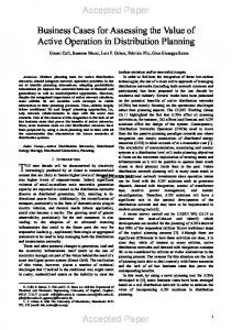
2. WINDING FAULTS DIAGNOSTICS 2.1 Experimental Setup and Simulation Transformer Model For the experimental investigation a three-phase, three limb transformer, of 6 kVA, 220/127 V, was used. The transformer has four windings per limb, where two of them were modified by the addition of a number of tappings connected to the coils, allowing for the introduction of different percentages of shorted turns at several locations in the winding, as shown in Fig. 1 for the phase R of the primary winding. A shorting resistor was connected at the terminals of the faulty subwinding, whose value was chosen so as to create an effect strong enough to be easily visualized, but simultaneously big enough to limit the short-circuit current and thus protecting the test transformer from complete failure when the short is introduced. If the fault occurs in the primary winding, the short-circuited turns act as an autotransformer load on the winding, as shown in Fig. 2(a), where Rsh represents the fault impedance. However, if the fault takes place in the secondary winding, the short-circuited turns act as an ordinary double winding load, Fig. 2(b), [20]. The experimental study of winding inter-turn short-circuits presents some inherent difficulties: the current in the shorted turns must be limited to the rated current of the winding and the tappings location of the test transformer does not allow the introduction of a small number of shorted turns, which, in this case, is limited to 5% (11 turns) of the whole winding (Fig. 1). Therefore, a detailed analysis of these phenomena can be better investigated by the additional use of a suitable simulation transformer model. For that purpose, a coupled electromagnetic transformer model was developed [26], which is based on the combination of both magnetic and electric lumped parameters equivalent circuits. The concept of duality is not used and the magnetic circuit of the transformer is not converted into analogous electrical equivalents. This allows the transformer to be defined and simulated in its natural electromagnetic environment so that cause-and-effect relationships can be closely investigated [27]. The coupled electromagnetic transformer model consists in the combination of both magnetic and electrical equivalent circuits (Fig. 3 and Fig. 4, respectively), in order to obtain the flux-current (-i) relationships:
λ Li
(1)
dλ dt v R i
(2)
The faults are introduced in the model by dividing the affected winding into two parts, which represent the healthy and the faulty subwindings, as shown in the equivalent circuits of Fig. 2. The pertinent fault equivalent circuit is then introduced in the magnetic 4
equivalent circuit (leading to three magnetomotive forces in the faulty phase, Fig. 5) and in the electric equivalent circuit (leading to other several changes, Fig. 6). A detailed description of the model implementation is given in [26]. For the results presented in this paper an YNyn0 transformer winding connection and a resistive load (Fig. 4) were considered.
Fig. 1. Location of the tappings for transformer primary winding (phase R).
(a)
(b)
Fig. 2. Equivalent circuits for a fault occurring in the: (a) primary winding; (b) secondary winding (phase R).
(a)
(b) Fig. 3. (a) Flux distribution in a three-phase, three-limb, two-winding, core type transformer, assuming a slightly greater magnetomotive force in the inner windings. (b) Equivalent magnetic circuit (leakage fluxes not shown).
5
Fig. 4. Simplified equivalent electric circuit for the case of an YNyn0 connection and a resistive load.
Fig. 5. Equivalent magnetic circuit for the case of a primary-side faulty winding (phase R).
Fig. 6. Equivalent electric circuit for the case of a primary-side faulty winding (phase R).
2.2 Transformer Behavior With Incipient Turn-to-Turn Winding Faults Fig. 7(a) presents the waveforms of the primary-side line currents, for the case of 10 % of shorted turns in the phase R of the transformer primary winding (notation as per Fig. 2 and Fig. 4) and a balanced load condition. The occurrence of primary-side inter-turn short-circuits leads to an increment of the magnitude of the current in the affected winding, as compared to a healthy condition, which results in an unbalanced system of primary currents. For this reason, the magnitude of the primary neutral current (in1 = i1 + i2 + i3), is also affected. In the presence of the primary winding inter-turn short-circuits, the secondary-side currents do not present any relevant change as compared to the transformer's healthy operation, remaining an approximately balanced threephase system, as shown in Fig. 7(b), and, consequently, in2 = i4 + i5 + i6 0.
6
The current waveform in the shorted turns, ib, and the current waveform in the fault impedance, ix, are shown in Fig. 7(c). The current ib is approximately in phase opposition with i1, due to the autotransformer action of the shorted turns. The current in the short-circuit auxiliary resistor, ix, has a higher magnitude than ib, since ix = i1 ib. The input current in the affected winding can be divided in three terms: i1 i4 iexc1 ix
(3)
where i'4 is the secondary winding current referred to the primary-side, iexc1 is the excitation current and i'x is the current in fault impedance, also referred to the primary-side. Obviously, the first two terms are related with the healthy operation of the transformer, being the third a result of the shorted turns. The faulty current is reflected to the primary-side through the turns ratio between the number of shorted turns, Nb, and the total number of turns of the primary-side winding, Np: ix ix
Nb Np
(4)
As a result, the increase in the magnitude of the primary-side winding current, due to an incipient insulation defect, with only a few turns involved, is small, even if the faulty current is large, and it is very likely that the fault will remain undetected by the protection devices, until it progresses to a catastrophic failure. The severity of the fault depends not only on the number of shorted turns, but also on the value of the faulty current, which is limited by the fault impedance. In the case of secondary-side winding faults, the additional load produced by the shorted turns also results into an increment in the magnitude of the correspondent primary-side winding current, as compared to a healthy condition, as shown in Fig. 8(a). Again, the line currents of the secondary-side do not suffer any significant change with the introduction of the defect, Fig. 8(b). However, with this type of fault, the current in the shorted turns is in phase with the line current of the affected winding, as shown in Fig. 8(c), and it takes larger values than the current in the short-circuit auxiliary resistor. Similar results were obtained when the fault position along the winding is changed, for the same severity degree of the defect. Although the leakage reactance of the affected coil changes with the relative position of the faulty turns within the winding [20], [28]-[29], this variation is small as compared to the fault impedance, in the case of incipient insulation defects, and no significant changes are detected in the primary- and secondary-side transformer currents.
7
(a)
(b)
(c)
Fig. 7. Experimental test results for the case of 10% of shorted turns in the primary winding (phase R): (a) primary-side current waveforms; (b) secondary-side current waveforms; (c) current waveforms in the affected winding.
(a)
(b)
(c)
Fig. 8. Experimental test results for the case of 10% of shorted turns in the secondary winding (phase R): (a) primary-side current waveforms; (b) secondary-side current waveforms; (c) current waveforms in the affected winding.
2.3 Supply Current Park’s Vector Pattern As a function of mains phase variables (i1, i2, i3) the transformer current Park's Vector components (iD, iQ) are given by: iD
2
3 i1 1
6 i2 1
iQ 1
2 i2 1
6 i3
2 i3
(5)
(6)
Under ideal conditions, the three-phase currents lead to a Park's Vector with the following components: iD iQ
6 2 IˆM sin t
6 2 IˆM sin t 2
(7)
(8)
where ÎM is the maximum value of the on-load exciting current (A), is the angular supply frequency (rad/s) and t is the time variable (s). The corresponding representation is a circular locus centered at the origin of the coordinates. Under abnormal conditions equations (7) and (8) are no longer valid and consequently the observed picture differs from the reference pattern. The operating philosophy of the Park's Vector Approach is thus based on identifying unique signature patterns in the figures obtained, corresponding to the transformer current Park's Vector representation. 8
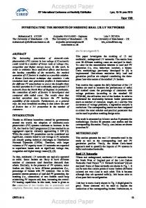
Fig. 9 presents the experimental primary-side phase current Park's Vector patterns, for several percentages of shorted turns in the primary windings and for different faulty phases. For all the cases in Fig. 9, the auxiliary short-circuit resistor was adjusted in order to limit the magnitude of the current in the shorted turns, Îb, to the rated magnitude of the current in the affected winding, Î1n. The primary-side phase current Park's Vector pattern, corresponding to the healthy operation, differs slightly from the circular locus expected for ideal conditions, due to, among others, the non-linear behaviour and asymmetry of the magnetic circuit. The occurrence of primary-side inter-turn short-circuits manifests itself in the deformation of the primary-side phase current Park's Vector pattern corresponding to a healthy condition, leading to an elliptic representation, whose ellipticity increases with the severity of the fault and whose major axis orientation is associated to the faulty phase. Similar conclusions, concerning the transformer supply current Park's Vector patterns, can be drawn for the occurrence of secondary inter-turn short-circuits, under the same load conditions and winding connections. The transformer secondary-side current Park's Vector pattern does not provide any indication about inter-turn short-circuits that may occur, either in the primary or in the secondary-side of the transformer. However, it plays a very important role for discriminating the presence of unbalanced loads. Consider, for example, the case of an unbalanced load with RL2=RL3=RL1/3.5 and, simultaneously, 5 % of shorted turns in the primary winding of phase R. From the resultant primary-side current Park's Vector pattern, shown in Fig. 10(a), it is difficult to detect the fault, being necessary to make use of the secondary-side current Park's Vector pattern to recognize the unbalanced load condition of the transformer. Consequently, with this diagnostic technique, it is difficult to discriminate between unbalanced loads and winding faults.
(a)
(b)
(c)
Fig. 9. Experimental primary-side phase current Park's Vector patterns for the case of an YNyn0 connection and a balanced resistive load, with several percentages of shorted turns in the primary windings and for different faulty phases: (a) phase R; (b) phase S; (c) phase T.
9
(a)
(b)
Fig. 10. Experimental primary and secondary-side winding currents Park's Vector patterns (a) and on-load exciting current Park's Vector patterns (b), for the case of an YNyn0 connection, an unbalanced resistive load and 5 % of shorted turns in the primary winding (phase R).
2.4 On-Load Exciting Current Park's Vector Approach To overcome the above-mentioned difficulty, an improved diagnostic technique was implemented, which consists in the analysis of the on-load exciting current Park's Vector pattern, being therefore unaffected by the transformer load condition. The on-load exciting current waveforms are computed by adding the primary and secondary winding currents, both referred to the primaryside. For the YNyn0 winding connection (Fig. 4) the on-load exciting currents are: ie1 i1 i4 N 2 N1 ie 2 i2 i5 N 2 N1
(9)
ie3 i3 i6 N 2 N1
For the case of other transformer connections, the on-load exciting currents can be obtained by using the same basic principle, but with slightly different computations. The formulas for the calculation of the on-load exciting currents for the cases of the DYn5 and Ynzn5 winding connections are presented in the Appendix A. With this approach the on-line feature of the former diagnostic technique is maintained. Fig. 11(a) presents the on-load exciting current Park's Vector pattern for the case of an YNyn0 winding connection and for a healthy operation of the transformer. This pattern also differs from the circular locus expected for an ideal situation, due to, among others, the non-linear behaviour and asymmetry of the magnetic circuit. This is a well known phenomenon, which is revealed by the unbalanced and distorted nature of the exciting currents obtained from any three-phase no-load test. In fact, the exciting current Park's Vector pattern, obtained at no-load conditions, presents the same characteristics, as shown in Fig 11(b). For the same case presented above, concerning the simultaneous occurrence of unbalanced loads and winding faults, the resultant on-load exciting current Park's Vector pattern can be seen in Fig. 10(b), from which the fault is clearly detected. The same operating philosophy of the supply current Park's Vector Approach can again be applied to identify the severity and the phase location of the fault. Additionally, the on-load exciting current Park's Vector Approach enhances the fault detection sensitivity, as compared to the former diagnostic technique, as shown in Fig. 12. 10
For the case of an incipient fault, involving only two shorted turns (1%), but with Îb = 5Î1n, the supply current Park's Vector pattern does not provide any indication about the inter-turn short-circuit (Fig. 13(a)), whereas the analysis of the on-load exciting current Park's Vector Approach clearly reveals the presence of the fault, Fig. 13(b). Other experimental and simulation tests carried out for different types of the transformer windings connection lead to similar conclusions to the ones presented before [30].
(a) (b) Fig. 11. On-load exciting current Park's Vector pattern (a) and no-load exciting current Park's Vector pattern (b), for the case of an YNyn0 connection and healthy operating conditions.
(a) (b) (c) Fig. 12. Experimental on-load exciting current Park's Vector patterns for the case of YNyn0 connection and a balanced resistive load, with several percentages of shorted turns in the primary windings and for different faulty phases: (a) phase R; (b) phase S; (c) phase T.
(a) (b) Fig. 13. Simulated supply current Park's Vector pattern (a) and on-load exciting current Park's Vector pattern (b), for the case of a YNyn0 connection, a rated balanced resistive load and two shorted turns (1%) in the primary winding (phase R).
11
2.5 On-Load Exciting Current EPVA Signature The Extended Park's Vector Approach (EPVA) is based on the spectral analysis of the AC level of the current Park's Vector modulus: 2 2 ieD j ieQ ieD ieQ
(10)
Ideally, under healthy conditions, the EPVA signature will be clear from any spectral component, i.e., only a DC value is present in the current Park's Vector modulus. The occurrence of winding inter-turn short-circuits (on the primary or on the secondary-side) leads to an increment in the magnitude of the on-load exciting current in the affected phase, as compared to a healthy situation, which results in an unbalanced system of currents. Under these conditions the on-load exciting current Park's Vector modulus will contain a dominant DC level and an AC level, at twice the supply frequency (2f), whose existence is directly related to the asymmetries in the transformer. The amplitude of this spectral component is directly related to the extension of the fault. In this way, an indicator of the degree of asymmetry can be defined as the ratio between the amplitude of the spectral component at the frequency of 2f and the DC level of the on-load exciting current Park's Vector [25]. The proposed fault severity factor (SF) is thus expressed by: 2 2 magnitude ieD ieQ 2 f component SF 2 2 average ieD ieQ
(11)
Further details of the theoretical principles related with the EPVA can be found in [25]. Fig. 14 presents the EPVA signatures for the case of an YNyn0 winding connection, rated load conditions and for a healthy operation of the transformer. As stated above, under ideal conditions, the EPVA signature would be clear from any spectral component. However, in practice, a spectral component with a small amplitude, at a frequency of 2f (100 Hz), is present, which is originated by the same reasons responsible for the deformation of the exciting current Park's Vector pattern (Fig. 11).
(a)
(b)
Fig. 14. EPVA signatures of the on-load (a) and the no-load (b) exciting currents for the case of an YNyn0 connection and healthy operating conditions (experimental results). 12
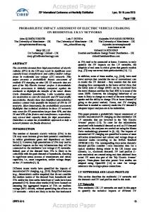
Several experimental tests were conducted in order to evaluate the transformer behavior under the occurrence of shorted turns, and maintaining the faulty current within safe values. However, due to the physical limitations of the test transformer using the available tappings locations, it is not possible to introduce a low severity fault (like a turn-to-turn fault), which is intended to be detected by the proposed diagnostic technique. For these reasons, it will be given more relevance to digital simulation results in this section. The EPVA signatures, for the case of two shorted turns in the primary winding of phase R and for several values of the current in the faulty turns (in terms of the rated current of the affected winding, I1n), are shown in Fig. 15. It can be seen that the amplitude of the 2f spectral component (100 Hz) increases with the severity of the fault, representing a good indicator of an insulation defect. Fig. 16 presents the evolution of the severity factor, given by (11), with the current in the two shorted turns (phase R). The values of the severity factor increase monotonically with the increase of the faulty current [25]. The results clearly indicate that the proposed diagnostic technique is sensitive to low level faults. In the experimental setup only medium/heavy severity fault tests can be performed. Fig. 17(a) shows the evolution of the severity factor with the number of shorted turns (phase R). Similar conclusions to the ones presented for the case of incipient faults can be drawn. The corresponding simulated results are also presented in Fig. 17(a), which are in close agreement with the experimental ones. Fig. 17(b) and Fig17(c) present the experimental and simulated tests results when the fault occurs in phase S and in phase T, respectively. The same overall behavior of the evolution of the severity factor, as a function of the number of shorted turns, is observed, irrespective of the faulty phase location. The proposed diagnostic method can be applied as a practical and effective on-line tool for computerized fault detection, providing a reliable and consistent fault severity measure. The method is general and can be applied for other types of transformer winding connections (as exemplified in the Appendix A). The severity factor is independent of the transformer's load conditions, since its computation is based on the on-load exciting currents, which are unaffected by the load level.
(a)
(b)
(c)
Fig. 15. EPVA signature for the case of two shorted turns in the primary winding of phase R, with the following values of the current in the faulty turns: (a) Îb = Î1n; (b) Îb = 2 Î1n; (c) Îb = 4 Î1n (simulated results).
13
Fig. 16. Evolution of the severity factor with the current in the two shorted turns (simulated results).
(a)
(b)
(c)
Fig. 17. Evolution of the severity factor with the number of shorted turns: (a) phase R; (a) phase S; (a) phase T.
3. Conclusions This paper presents the application of the on-load exciting current Extended Park's Vector Approach for diagnosing the occurrence of inter-turn short-circuits in the windings of operating three-phase transformers, which consists in the spectral analysis of the AC level of the on-load exciting current Park's Vector modulus. The proposed on-line diagnostic technique combines the advantages of three well known methods:
the former Park's Vector Approach, which combines the information contained in the three-phase system into only one quantity;
the on-load exciting current, which enhances the fault detection sensitivity;
the spectral analysis, which gives a more detailed insight into the results obtained by the Park's Vector [25].
Experimental and/or simulation test results were presented, which demonstrate the effectiveness of the diagnostic technique. The proposed diagnostic method can be applied using hand-held equipment or can be integrated into existing on-line continuous monitoring systems. Moreover, due to the low computation requirements, the EPVA technique can even be included in existing microprocessor-based differential protection systems. In either way, the on-load exciting current Extended Park's Vector Approach constitute a low-cost on-line diagnostic method, that will permit the cost-effective continuous monitoring of the unit, providing early fault detection, accurate trending information and reliable fault diagnosis.
14
Appendix A For the Dyn5 winding connection, Fig. A.1, the on-load exciting currents are: ie1 iL 4 1 1 0 iL1 i 1 0 1 1 i N 2 i e2 3 L 2 N L5 1 ie3 1 0 1 iL3 iL 6
(A.1)
For the YNzn5 winding connection, Fig. A.2, the on-load exciting currents are [30]: ie1 iL1 1 0 1 iL 4 i i N 2 1 1 0 i e2 L 2 N L5 1 ie3 iL3 0 1 1 iL 6
(A.2)
Fig. A-1. Transformer Dyn5 winding connection.
Fig. A-2. Transformer YNzn5 winding connection.
References [1] M. Wang, A novel extension method for transformer fault diagnosis, IEEE Trans. Power Delivery 18 (1), (2003) 164-169. [2] B. Sparling, Managing and extending the life of transformers, Electricity Today, (2000). [3] C. Myers, Transformers – conditioning monitoring by oil analysis, large or small; contentment or catastrophe, in proc. First IEE/IMechE International Conference on Power Station Maintenance - Profitability Through Reliability, 1998, pp. 53-58. [4] W.H. Bartley, Analysis of transformer failures, in proc. 36th Annual Conf. International Association of Engineering Insurers, 2003.
15
[5] M. Checksfield, A. Westlake, Experiences with operating and monitoring generator transformers, in proc. IEE Colloquium Transformer Life Management, 1998, pp. 4/1-4/7. [6] Z. Wang, Artificial intelligence applications in the diagnosis of power transformer incipient faults, Ph. D. thesis, Faculty of the Virginia Polytechnic Institute and State University, 2000. [7] C. Bengtsson, Status and trends in transformer monitoring, IEEE Trans. on Power Delivery 11 (3), (1996) 1379-1384. [8] M. Wang, A.J. Vandermaar, K.D. Srivastava, Review of condition assessment of power transformers in service, IEEE Electrical Insulation Magazine 18 (6), (2002) 12-25. [9] A.J.M. Cardoso, L.M.R. Oliveira, Condition monitoring and diagnostics of power transformers, Int. Journal of COMADEM 2 (3) (1999) 5-11. [10] A.J. Vandermaar, Condition assessment of power transformers, in: proc. IEEE Power and Energy Society General Meeting - Conversion and Delivery of Electrical Energy in the 21st Century, 2008, 1-5. [11] B.H. Ward, S. Lindgren, A survey of developments in insulation monitoring of power transformers, in: Conf. Record of the 2000 IEEE Int. Symposium on Electrical Insulation, 2000, 141-147. [12] CIGRE/SC 12/WG 05, An international survey on failures in large power transformers in service, Electra (88), (1983), 21-48. [13] H. Ding, R. Heywood, J. Lapworth, S. Ryder, Why transformers fail, Euro TechCon, 2009. [14] IEEE guide for protective relay applications to power transformers, IEEE Std. C37.91-2000. [15] E.A. Klingshirn, H.R. Moore, E.C. Wentz, Detection of faults in power transformers, AIEE Trans. 76, (1957) 87-95. [16] H. Wang, K.L. Butler, Modeling transformers with internal incipient faults, IEEE Trans. Power Delivery 17 (2), (2002), 500-509. [17] P. Barkan, B.L. Damsky, L.F. Ettlinger, E.J. Kotski, Overpressure phenomena in distribution transformers with low impedance faults: experiment and theory, IEEE Trans. Power Apparatus and Syst. 95 (1) (1976) 37-48. [18] C.W. Plummer, G.L. Goedde, E.L. Petit, J.S. Godbee, M.G. Hennessey, Reduction in distribution transformer failures rates and nuisance outages using improved lightning protection concepts, IEEE Trans. Power Delivery 10 (2) (1995) 768-777. [19] J.M. Lunsford, T.J. Tobin, Detection of and protection for internal low-current winding faults in overhead distribution transformers, IEEE Trans. Power Delivery 12 (3) (1997) 1241-1249. [20] S.A. Stigant, A.C. Franklin, The J&P Transformer Book, 10th Ed., Newnes-Butterworths, London, 1973. [21] C. Raux, C. Leconte, T. Gibert, Resistance of transformers to internal faults: synthesis of experimental results, in: Proc. of 10th International Conference on Electricity Distribution (CIRED 1989), 1989, pp. 71-75. [22] Z. Gajic, I. Brncic, B. Hillström, F. Mekic, I. Ivankovic, Sensitive turn-to-turn fault protection for power transformers, in: Proc. 32th Annual Western Protective Relay Conf., 2005. [23] O. Ozgonenel, E. Kilic, M.A. Khan, M.A. Rahman, A new method for fault detection and identification of incipient faults in power transformers, Electric Power Components and Systems 36 (11), 1226-1244.
16
[24] A.J.M. Cardoso, The Park's Vector Approach: a general tool for diagnostics of electrical machines, power electronics and adjustable speed drives, in: Record of the 1997 IEEE International Symposium on Diagnostics for Electrical Machines, Power Electronics and Drives, 1997, pp. 261-269. [25] S.M.A. Cruz, A.J.M. Cardoso, Stator winding fault diagnosis in three-phase synchronous and asynchronous motors, by the extended Park's Vector Approach, IEEE Trans. Industry Applications 37 (5) (2001) 1227-1233. [26] L.M.R. Oliveira, A.J.M. Cardoso, A permeance-based transformer model and its application to winding interturn arcing fault studies, IEEE Trans. Power Delivery 25 (3), (2010) 1589-1598. [27] R. Yacamini, H. Bronzeado, Transformer inrush calculations using a coupled electromagnetic model, IEE Proc. Sci. Meas. Technol. 141 (6) (1994) 491-498. [28] H. Wang, K.L. Butler, Finite element analysis of internal winding faults in distribution transformers, IEEE Trans. Power Delivery 16 (3), (2001), 442-428. [29] L. Satish, S.K. Sahoo, Locating faults in a transformer winding: an experimental study, Electric Power Systems Research 79 (2009) 89-97. [30] L.M.R. Oliveira, A.J.M. Cardoso, S.M A. Cruz, Transformers on-load exciting current Park's Vector Approach as a tool for winding faults diagnostics, in: Conf. Record of the 15th Int. Conf. on Electrical Machines (ICEM 2002), 6 pp, CD ROM.
17