Three-phase Three Legs Power Transformers Asymmetrical Modes Study for Zigzag Windings Connection. Bosneaga V., Suslov V. Power Engineering institute, Academy of sciences, Chisinau, Moldova
[email protected] for the case of isolated neutral on the medium voltage side and Abstract. Based on the previously proposed model the simulations grounded neutral on the low voltage side. For calculations let were made and characteristic features of steady asymmetric use the catalogue data of Minsk (Belorussia) transformer plant modes of three-phase core type (three leg) transformer were (http://metz.by/) for distribution transformers for direct investigated for zigzag winding connection, taking into sequence. For the transformer type TMG, rated power 100 kVA, consideration the electromagnetic coupling of windings, located on different legs. Calculations and analysis were conducted based on rated voltages 10/0.4 kV we have the following data: no load distribution transformer 100 kVA, 10/0.4 kV and include the most (excitation) current I0 =2,6%, short-circuit voltage Usc= 4,7 %, typical steady unbalanced conditions, arising at various short no load active power losses Р0=270 W, short circuit losses circuits, including those, accompanied by the presence of zero Рsc=2270 W. sequence magnetic flux. For the considered modes vector In addition, for this transformer the manufacturer provided diagrams of currents and voltages, as well as the relative values of measured from the high voltage (HV) side zero sequence the magnetic flux were constructed, which provide a clear visual impedance (for the scheme Y/y0) Z0 = 1.3 Ohm, and active representation of their features. It was demonstrated, that if the power losses at no load conditions P = 2 kW. Based on these 0 numbers of secondary windings turns are unequal, zigzag scheme data, in accordance with known formulas (see for example [22, no longer has advantages in asymmetric modes. These advantages also disappear at single-phase short-circuit of one secondary pp. 185-190]), one can calculate effective (RMS) values of the winding. Additional measures should be taken for the reliable windings rated currents for HV and low voltage (LV) sides: IHV protection against such short-circuits and prevention of = 5.8 A and ILV = 152 A, excitation current on HV side I0 = 0.15 A, rated windings voltages on HV and LV sides UHV=5.77 transformer damage. kV and ULV = 127 V, resistances and winding’s pairs shortIndex Terms- Power Transformer, core type, three limbs, circuit reactance, as well as all other variables, needed to asymmetric modes, zigzag, zero sequence, magnetic flux. elaborate the model. A similar version of the transformer is considered, for I. INTRODUCTION example, in [11], [12]. In [12] it is presented some data on the values of short-circuit currents for different windings Investigations and calculations of power transformers connections of distribution transformers with highest voltage of asymmetrical modes were conducted in many publications, the 6 kV, including for zigzag diagram, but for a correct comparison basics were laid in the classic books by Petrov G.N., Voldek with results, obtained here, it is necessary to have more detailed A.I., Vasiutynski S.B., [1]-[4], etc., then the study was data on transformers parameters, used in [12]. For greater continued in [5]-[10], etc. (the list is not exhaustive). clarity, let us present the results of calculations not in the form Nevertheless, the publications, developing various aspects of the of tables with values, but rather in the form of vector diagrams problem, including the creation of new models of three-phase (VD), and numerical values – only as needed. On Fig. 1, 2 are transformers continue to appear, including in the recent years shown the voltages of the primary and secondary windings of [13]-[20]. However, there is no publication where it is discussed transformer with zigzag diagram in initial symmetric mode (for in detail asymmetric modes for the scheme with zigzag windings the case, when the turns numbers of both secondary windings, connection. To perform this work a three-phase model for three connected in zigzag, are the same). The windings, located on the limb core transformer, proposed by the authors and described in same limb and belonging to one of the phases are designated by [21] was used. the letters A, B, C, the numbers 1, 2, 3 refer to the primary and secondary windings. Accordingly, the loads voltages include the II. CALCULATION ANS ANALASYS OF ASYMMETRIC MODES notation of windings, which are connected together to obtain the corresponding load voltage (wherein the first is recorded the Let us consider with the help of elaborated model typical winding, connected to the neutral point, for example, a load features of steady asymmetrical modes of three phase, core type voltage U A2B3). distribution transformer with zigzag windings connection Y/z0
978-1-4673-6487-4/14/$31.00 ©2014 IEEE
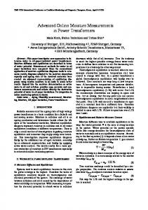
On subsequent figures the obtained results are given in the form of vector diagrams for various asymmetrical modes calculations. Fig. 3 shows the voltages of LV windings and loads for the single-phase short circuit to ground (shorted load is A2B3), as initial mode is taken the symmetrical loading according to Fig. 1, 2. As it can be seen from VD on Fig. 3, voltages of "healthy" loads UB2C3 and UC2B3 (shown in dashed lines) are somewhat less than the nominal voltage, and the phase angle is more than conventional of 120°. Voltages system of secondary windings, forming zigzag (voltage of primary windings A1,B1,C1 look very similar, so are not shown) is distorted, wherein the voltages on the shorted windings A2,B3 (as expected ) are equal and much less, than nominal value. The voltages of remaining windings A3,B2, forming “healthy loads”, are much lower than the nominal value of 127 V and have a phase shift much less than normal of 120°, and the voltages of windings C2, C3 are also equal, and their value is close to nominal value. Current of one load phase short-circuit, obtained here by calculation, is equal to 113 A, this value is approximately consistent with the result (102 A), presented in [12], taking into account that in [12] the voltage was equal to 6 kV. Pattern of magnetic fluxes in the limbs of magnetic core for
this mode is shown in Fig.4, from which it is seen, that the sum of limbs fluxes is close to zero, and hence the zero sequence flux in the air under these conditions is missing, which, as is known, is a significant advantage of the zigzag connection. In addition, the calculations fulfilled confirm that the star of HV windings voltages remains symmetrical, and no displacement of the neutral is observed. It should be noted, that these beneficial
1 r.u.
Fig.4. Relative values of limb’s magnetic fluxes at one phase short-circuit.
Fig 1. VD of Y-connected primary windings voltages for symmetric load conditions.
Fig.2. VD of loads and secondary windings voltages for zigzag connection at symmetrical conditions.
200 V
properties of zigzag connection only take place in case of the equal numbers or turns of windings, constituting zigzag (see Fig. 2, voltages UA2=UB3 and so on.). At Fig.5, 6 are presented VD for the considered mode of short-circuit in one phase of load, corresponding to the ratio of secondary windings turns of 2:1 (in this case the angle between load and respective winding voltages will be less than 30°, and will be close to 15°). From Fig.5, which shows the relative values of fluxes in the core limbs, it follows the appearance in this case of significant zero sequence flux. Besides, the displacement of neutral point appears at HV side of the transformer. Dramatically changes not only the picture of magnetic fluxes in the limbs, but also the VD of windings voltages and load voltages (see Fig.6).
300 V
Fig. 3. VD of loads and secondary windings voltages at short-circuit in one phase of load.
Fig. 5. Relative values of fluxes in the core limbs at one phase of load short-circuit and the ratio of secondary windings turns of 2:1.
Fig.6. LV windings and loads voltages at one phase of load shortcircuit and the ratio of secondary windings turns of 2:1.
Thus, at different numbers of secondary windings turns, forming "shoulders" of zigzag connection, the beneficial properties, inherent to this scheme in asymmetric modes of operation, practically are lost. Let consider next the less likely, but also possible mode of short-circuit on the LV side between the two arms of load without earth. At such fault, obviously, respective voltages will have the same value (UА2В3=UВ2С3). Fig. 7 shows VD for the windings and loads voltages on the LV side at short-circuit between the two arms of loads without earth. The voltage on short-circuited loads sharply decreases and three phase voltages system on the loads is greatly distorted.
The largest short-circuit current in this mode is reached in the phase B of the power supply source and is equal to 150 A. Next, let consider short-circuit of two phases of load to ground. In this case two voltages of load “shoulders” are equal to zero (UА2В3=UВ2С3 =0). At Fig.9, 10 are presented VD, obtained for the considered case. At Fig .9 are presented the LV side windings voltages, it is obvious, that at such fault windings voltages are decreased further in comparison with previous case, but the power source currents still remain balanced and become even more symmetrical, although the largest value of the fault current (see Fig. 10) remains practically the same, as in previous case. Power source currents in this mode are more symmetrical, than at short-circuit of two phases of load without ground, and also are balanced. Let consider further for completeness specific unbalanced mode, associated with possible internal fault in transformer namely, short-circuit to ground of one secondary winding on LV side, adjacent to the neutral (in this case, in phase A). At Fig.11 - 14 are presented VD, obtained as a result of calculations, made for the considered case. As follows from Fig.11, this shows
250 V
Рис.7. Windings and loads voltages on LV side at shortcircuit between two arms of loads without ground.
Fig . 8. VD for the source currents on HV side at short-circuit between the two arms of loads without earth.
It is also seen on the VD, that the voltages on B2 and B3 windings coincide and are almost invisible because of their relatively small value. Besides, the voltages on all LV side windings are much lower, than the nominal one. As it could be seen from Fig.8, the sum of source phase currents is zero, which is understandable, since the HV side has no way for the flow of zero sequence current. Due to calculations performed, the neutral current on the LV side is also zero, and, respectively, there is no zero sequence current in the secondary windings and no zero sequence flux.
Fig. 9. LV side windings voltages at short-circuit of two phases of load to ground.
Fig. 10. Source currents on HV side at short-circuit between two “arms” of loads with ground.
Fig.11. Fault currents from the power source at short-circuit of phase A secondary winding (connected to neutral).
Fig.12. LV side windings and loads voltages and currents at short-circuit to ground of phase A secondary winding.
the fault currents from the power source, they are relatively small in comparison with usual short-circuit currents (approximately twice bigger than rated current), so, at such fault
Fig.13. HV side windings voltages at short-circuit to ground of phase A secondary winding.
Fig.14. Relative values of limbs magnetic fluxes and total zero sequence air flux at short-circuit to ground of phase A secondary winding.
the usual protection will not work, but the transformer will be overloaded with these currents and could be damaged. So, it would be desirable to provide protection against this regime. Loads currents and voltages (see Fig. 12) in this mode are close to symmetric; the voltages of short-circuited phase A are close to zero (so, they are not shown on VD), but the voltages of "healthy" windings B2, B3 and C2, C3 are strongly shifted by phase relative to their normal positions. From Fig. 13, which shows the voltages of the primary star connected windings with isolated neutral, it is seen, that the system of primary windings voltages is sufficiently asymmetrical, has essential shift of the neutral point and is similar to the VD of secondary voltages. Furthermore, in this mode, due to calculations made, (see VD with results on Fig.14) significant zero sequence flux, caused by unbalanced windings currents, appeared. III. CONCLUSIONS 1. Based on elaborated model the calculation of modules and angles of windings currents and voltages in three-phase three limb core transformer with "zigzag" connection of secondary windings at various short-circuit modes was performed. Electromagnetic coupling between windings on different limbs, based on zero sequence parameters, was considered. Obtained vector diagrams for windings voltages and currents and relative values of magnetic fluxes give clear visual representation of different asymmetric modes peculiarities. 2. At usual single-phase and two-phase short-circuits the "zigzag" connection (at equal secondary windings turns number) ensures absence of zero-sequence current and flux and, accordingly, less distortion of voltages and currents (in comparison with Y/y and D/y connections) at asymmetric shortcircuits and loads. However, if the numbers of secondary windings turns are unequal, this scheme no longer has mentioned advantages. Furthermore, these advantages also disappear at single-phase short-circuit of one secondary winding, that, in turn, seemingly means, that a similar effect will also occur at internal short-circuits between loops in the windings. 3. The currents, arising from short-circuit of one secondary winding, are approximately twice bigger than rated load currents and are significantly smaller, than usual short-circuit currents. Due to this, they are insufficient for the reliable operation of protection against short-circuits, so this may require additional measures to protect against such faults and prevent transformer damage. 4. To enable more accurate accounting of asymmetric modes processes associated with the appearance of zero sequence current and magnetic flux, transformer manufacturers should present in the catalogue data sheets of transformers, along with
parameters for the positive sequence, also their measured values for the zero sequence, due to the fact that the latter are difficult to obtain by calculation. REFERENCES [1] G.N. Petrov. Transformers. Fundamentals of theory. Vol.1, GEI, 1934, 445 pp. (In Russian). [2] G.N. Petrov. Electrical machines. In 3 parts. Part 1. Introduction. Transformers. M. , Energia, 1974, 240 pp.(In Russian). [3] A.I. Voldek. Electrical machines. – L.: Energia, 1978, 832 pp.(In Russian). [4] S.B. Vasyutinsky. Problems of theory and design of transformers. L., Energia, 1970, 432 pages. (In Russian). [5] B.N. Sergeenkov. Electrical machines. Transformers. Edited by Kopylov I.P., M. Vishaia shkola, 1989, 352 pp. (In Russian). [6] E.I. Zabudski. Electrical machines. Part 1. Transformers. M , 2002, 168 pp.(In Russian). [7] S.B. Losev, A.B. Chernin. Calculation of electrical values in asymmetric modes of electrical systems. M., Energoatomizdat, 1983, 527 pp. (In Russian). [8] A.P. Berman. Calculation of asymmetric modes of electrical systems using phase coordinates. Elektrichestvo, 1985, number 12 , pp. 6-12. (In Russian). [9] A.M Guseynov. Calculation of asymmetric steady-state modes in complex systems using phase coordinates. Elektrichestvo, 1989, Nr. 3.(In Russian). [10] D.D. Karasev, E.D. Karasev. Calculation of electrical networks with “FAZAN” software. Editor A.I. Artemov. Moscow: Moscow Power Engineering Institute, 1989.(In Russian). [11] B. Fishman, A. Fedorovskaia. Power transformers 10 (6 ) / 0.4 kV. Areas of application of different connection schemes. Novosti Elektrotehniki, Nr.5, 2006. (In Russian). [12] B. Fishman, A. Fedorovskaia. Power transformers 10 (6 ) / 0.4 kV. Areas of application of different connection schemes . Novosti Elektrotehniki, Nr.6 (60), 2009. (In Russian). [13] G.A. Evdokunin, M.V. Dmitriev. Transformers in the electrical network. Simulation of transient processes taking into account the configuration of magnetic system. Novosti Elektrotehnik" Nr. 5 (53), 2008. (In Russian). [14] V.P Zakaryukin, A.V. Kriukov. Complicated asymmetric modes of electrical systems. Publisher Irkutsk State University, 2005 - 274 p. (Transformer model – at page 45.), (In Russian). [15] A.S. Gusev, S.V. Svechkarev, I.L. Plodisty. Universal mathematical model of three-phase transformers and autotransformers. Bulletin of the Tomsk Polytechnic University. 2007. Vol. 311. – Nr. 4, pp.77-81. (In Russian). [16] V.A. Martynov. Unbalanced modes of power transformers with windings connection Y/y0. Bulletin of Irkutsk State Power University, issue 2, 2009, pp. 15.(In Russian). [17] M. Iu. Pustovetov. Mathematical model of three-phase transformer, Proceedings of Tomsk Polytechnic University. 2012. Vol. 321. Nr.4. (In Russian). [18] Three-Phase Transformer Inductance Matrix Type (Two Windings). 2012. URL:http://www.mathworks.com/help/toolbox/physmod/powersys/ref/threephas etransformerinductancematrixtypetwowindings.html (date of access: 06.04.2012). [19] Three-Phase Transformer 12 Terminals. 2012. URL:http://www.mathworks.com/help/toolbox/physmod/powersys/ref/threephasetransformer12ter minals.html (date accessed: 06.04.2012). [20] URL:http://www.mathworks.com/help/physmod/powersys/ref/threephasetransformer-inductancematrixtypethreewindings.html (date of access: 20.09.2013). [21] V.A. Bosneaga, V.M. Suslov. Investigation of asymmetrical modes of three-phase three leg transformer with windings connection in zigzag.(In Russian) (http://journal.ie.asm.md/en/contents/elektronnyij-zhurnal-n-3232013). [22]Electrical Engineering Handbook: In 3 volumes, Vol. 2. M, Energoatomizdat , 1986, 712 pp.(In Russian).