Jul 12, 1998 - 672-683. West Palm Beach, Florida. Summer 2001. Rates and Processes of Marsh Shoreline Erosion in. Rehoboth Bay, Delaware, U.S.A..
672-683
Journal of Coastal Research
West Palm Beach, Florida
Summer 2001
Rates and Processes of Marsh Shoreline Erosion in Rehoboth Bay, Delaware, U.S.A. Reed A. Schwimmer Department of Geological and Marine Sciences Rider University Lawrenceville, NJ 08648, U.S.A. ABSTRACT
.tllllllllt.
eusu b-Ut ~ ~~
--+4
?'
_
SCHWIMMER, R.A., 2001. Rates and Processes of Marsh Shoreline Erosion in Rehoboth Bay, Delaware, U.S.A. Journal of Coastal Research, 17(3),672-683. West Palm Beach (Florida), ISSN 0749-0208. The marsh shoreline in western Rehoboth Bay, Delaware, is rapidly eroding due to wave attack. A 30-90 em vertical scarp characterizes the shoreline and exposes the present-day rootmat and the underlying mud unit. Using an Electronic Total Station surveying instrument, marsh erosion rates were determined for six 10-meter shoreline sections. Over a three-year period, averaged erosion rates ranged from 14 cm/yr to 43 ern/yr. Three styles of shoreline erosion were observed. (1) Cleft and neck formation-V-shaped notches are cut into an initially "straight" shoreline. Between adjacent clefts, marsh necks, up to three meters in length, occur creating an undulatory shoreline geometry. (2) Neck cut-off-marsh necks can be cut off from the marsh creating a small marsh "stack." (3) Undercutting with rootmat toppling-wave action erodes the lower mud unit faster than the overlying rootmat creating an overhang that eventually topples into the bay. At a decimeter scale, shoreline geometry is due to successive changes in erosional style. In contrast, the geometry of a fringing marsh shoreline over several hundred meters is likely controlled by antecedent topography and not by lateral variations in erosion rates. Rates of erosion are correlated with wave power. The wave power potentially impinging on nine selected marsh shoreline sites was calculated using wind, bathymetric, and fetch data. Erosion rates for each site were plotted against estimated wave powers producing a regression equation that allows erosion rates to be predicted. As wave power increases, the rate of erosion increases. ADDITIONAL INDEX WORDS:
Coastal retreat, recession, wave power.
INTRODUCTION The areal distribution of salt marshes along the Delaware coast has not been static. As marshes evolve, they may either expand or diminish through time, a process which may directly affect the ecology and economy of a region. With estimates of global sea-level rise from about 0.2 m to over 1.0 m by the year 2100 (WIGLEY and RAPER, 1992; IPCC, 1995; TITUS and NARAYANAN, 1995; HOUGHTON, 1997), the salt marshes of Delaware and elsewhere will most certainly be affected. The loss of these ecologically important areas will have a lasting effect on not only the abundance and diversity of wildlife in the coastal environment but also on the condition and preservation of the Delaware bays and of the coastal communities. Understanding the mechanisms of marsh shoreline erosion is therefore an important step in understanding how the coastal environments will change over time and how this will affect coastal communities. Previous studies of shoreline erosion in Delaware Bay (MAURMEYER, 1978; HARDISKY and KLEMAS, 1983; PHILLIPS, 1985, 1986a, 1986b; KRAFT et al., 1992; FRENCH, 1990), along the Atlantic coastline of Delaware (GALGANO, 1989; KRAFT et al., 1992), in Rehoboth Bay (SWISHER, 1982) and in Chesapeake Bay (ROSEN, 1977, 1980; SPOERl et al., 1985; DALRYMPLE et al., 1986; KEARNEY and STEVENSON, 1991; DOWNS et al., 1994; WRAY et al., 1995; WILCOCK et al., 98263 received 12 July 1998; accepted in revision 17 September 2000.
1998) have clearly demonstrated that shoreline erosion is a significant coastal process in the mid-Atlantic region. The majority of the shorelines that were examined, however, were sandy beaches or coastal bluffs and not marsh shorelines. Furthermore, erosion rates from these studies were estimated over relatively large distances using primarily aerial photographs and NOS Coastal Survey Maps (T-sheets) to map shoreline changes. Consequently, they do not provide details of how the shoreline is changing over relatively short distances such as a few meters. In contrast, this study presents a detailed investigation of the rates and processes of wave erosion along a marsh shoreline. In addition, I propose that the rate of marsh shoreline erosion may be expressed as a function of wave power (energy flux). Consequently, wind, bathymetric, and fetch data are used to develop a predictive tool that can be used to estimate marsh shoreline erosion rates for different geographical settings. Wave attack is considered to be the dominant erosional process in the study area. Human activities that may affect the shoreline, such as channel dredging and bay maintenance projects did not occur in the study area during the time of the investigation. Clam digging was rarely observed in the area and never on or adjacent to the shoreline scarp. Boat wakes and ice formation, as discussed below, are not considered to be a significant factor in shoreline erosion in the area. In addition, longshore currents are unlikely to erode the shoreline because the highly irregular geometry of the shore-
Marsh Shoreline Erosion
673
REHOBOTH
BAY
A MARSH ISLAND
REHOBOTH BAY
Q
c o
INDIAN RIVER BAY
38°40'
E
INDIAN
o
RIVER INLET
I
~ U P LAN DS
400 m
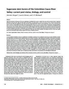
Figure 2. Location of the six survey sites along the Horse Island marsh and Marsh Island shorelines.
Figure 1. Map of th e Delaware Inland Bays illustrating location of study area and other physical features.
line, where waves do not break before the shoreline but rather hit squarely against the scarp, inhibits strong, persistent currents from forming. Also, tidal action is not considered to be a significant erosional process as the tidal range is relatively small, approximately 30 em, in Rehoboth Bay. Consequently, it is the relentless wind-driven waves that jar the sediment loose from the scarp and transports the debris away allowing the shoreline to retreat.
STUDY AREA Horse Island marsh and Marsh Island are located on the northwestern margin of Rehoboth Bay , Delaware (Figure 1). Five sites were chosen on Horse Island marsh and one on Marsh Island to survey the geometry of the shoreline (Figure 2). Horse Island marsh is bounded by two upland interfluves and is approximately 100 ha in size. Horse Island is a prominent upland hill or "island," surrounded by marsh, and presently is part of the shoreline forming a short stretch of sandy beach . Vegetation on the marsh consists of patches of Spartina alterniflora, Spartina patens, and Distichlis spicata . Marsh Island is located about 400 meters east of Horse Island marsh and is comprised solely of Spartina alterniflora. The island is approximately 0.9 ha in size and is presently the largest marsh island in Rehoboth Bay. The shorelines of Horse Island marsh and of Marsh Island are characterized by a vertical scarp, with an approximate
range of 30-90 em in height (n = 100, mean = 70 em, standard deviation = 13 em), which exposes the rootmat and the underlying muds (Figure 3). The relatively unconsolidated muds erode faster than the overlying rootmat. As a result, the rootmat commonly forms an overhang (Figure 3). The length of the overhang ranges from 0 em (vertical scarp) to about 50 em (n = 50, mean = 24 em, standard deviation = 13 em). Sandy beaches occur where the eroding shoreline has intersected upland areas. This occurs at Horse Island and at the interfluve marking the southern extent of Horse Island marsh (Figure 2).
METHODS Erosion Rates A Topcon Electronic Total Station was used to survey the marsh shoreline at six sites within the study area. The prism rod was moved along the shoreline at intervals of approximately 10 to 30 em depending on the geometry of the shoreline. Wooden posts were driven into the marsh, approximately 10 m from each other, at each survey site to serve as benchmarks. The benchmarks served as stable reference points that allowed subsequent surveys to be graphically overlain in order to discern a change in shoreline position. The results were then plotted and an average erosion rate was calculated by dividing the area between two consecutive shorelines by the average shoreline length. The rates were then normalized to a one-year time period. The geographic information system ARCIINFO was used to digitize the graphs and to estimate the eroded area and shoreline length. Error Estimate for Erosion Rates Because shoreline positions were surveyed in the field, many of the potential errors that are associated with using historical maps and aerial photographs (see CROWELL et al.,
-Journal of Coastal Research, Vol. 17, No.3, 2001
674
Schwimmer
Figure 3. View of the Horse Isla nd ma rs h shore line illu st rating the erosiona l sca rp a nd t he rootmat over hang. Note that the marsh neck next to the meter stic k in the foreg roun d is beginn ing to top ple due to excessive u nd ercutting.
1991), to docum ent shore line changes, do not a pply. Th e pr ecision of th e total station coupled with a morph ology that help s defin e the shoreline edge (a vertical marsh sca rp vers us a gently sloping beach face), provides a high degr ee of pr ecision for locatin g shore line positi ons. In spite of th e high pr ecision , survey ing can realisticall y only cover relati vely sma ll stre tches of shoreline and long-term histori cal changes cannot be docum ented . Th e sources of erro r for this meth od can be broken down into three areas.
Electronic Total Station Each survey was initia te d and closed on the ben chm arks (us ing a nail head in ea ch woode n post to accura tely relocate th e pri sm rod). Th e coordina tes of eac h benchmark ty pica lly varied less th an 0.6 em. Marsh surface inst ability for th e tripod, changi ng temp er atures through out the day, and wind gusts movin g th e pri sm rod , most likely account for most of this error . Determining the Edge of the Shoreline Th e later al exte nt of th e rootm at was used as the edge of th e shore line. Often th e sedime nt between the roots at the edge of th e ero ded sca rp was eroded leaving only a flimsy network of root s. Thi s would mak e placin g the pri sm rod difficult as th er e was no firm soil to set the rod. This area of exposed root s, if pr esen t , would likely give an er ror ra nge of ::':: 2 em.
Digitizing Error Ass uming a 0.25 mm operator er ror and 0.25 mm digitiz er error (C ROWELL et a!', 1991), the tota l error ra nge would be a pproxima tely ::':: 1.5 em . Overall, the calculated eros ion rates have an esti ma te d combined error ra nge of ::':: 4 em. Using Wave Power to Predict Erosion Rates SUNAM URA (1992 ) summa rized previous shore line erosio n studies that have used differen t param et ers to asso cia te with erosion ra tes, such as wave height , compressive st re ngth of the shoreline material , beach elevation, and cliff height. RoSE N (1977, 1980) studied how va riations in tidal ran ge influence eros ion rates as well as va riations in shore line ty pe. W ILCOCK et al. (1998) rela te d erosio n rates to variations in t he ratio of wave pr essure and cohes ive stre ngth of the shorelin e material. As wave attack is the likely cause of shoreli ne erosion, wave power was the va ria ble chose n to pr edict erosion ra tes in th is st udy. Ind eed , SPOERl et a!. (1985) stated t hat wave power is lik ely the most imp ort ant factor in predicting rates of shore line erosio n. H EQUETIE and Ruz (1991) fou nd that landward migr ation rates of barrier isla nds are well correlated wit h wave power . GELINAS an d Q UIGLEY (1973) and KAMPHUIS (1987 ) previously used wave power to correla te with erosion ra tes along the north shore of Lak e Eri e. These t hree previous st udies, however , focused on beach shorelines and glacial till bluffs and not marsh shore lines.
Journal of Coast al Resear ch, Vol. 17, No. 3, 2001
Mar sh Shoreline Er osion
75° 10'
O·
~ EROSION SITE
a I
8
675
16
km
NEW
JERSEY
-i--
EGG ISLAND POINT
---'i-----1 90 ·
DELAWARE DELAWARE BAY
CAPE MAY
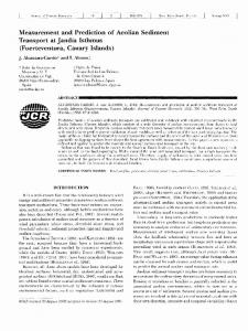
180· Figure 5. Rose diagram of the Dover Air Force Bas e wind data illustrating the frequency of winds from sixteen directions. Each wind direction includes data from all recorded wind speeds.
MARSH
I~
REHOBOTH BAY
38°40'
3 ~Om
Figure 4. Location map of the nine st retches of shoreline used to rela te wave power to erosion rate.
Nine stretches of shoreline were chosen from previous studies to test the relationship between wave power and erosion rates: three from the Horse Island marsh area (SWISHER, 1982), and six from Delaware Bay (MAURMEYER, 1978; PHILLIPS, 1985; FRENCH, 1990) (Figure 4). These stretches were selected because long-term erosion rate data were previously reported for each site. The Delaware Bay sites were chosen in order to include areas that have erosion rates that are significantly greater than the Rehoboth Bay sites. These six sites are believed to represent the only marsh shorelines in Delaware Bay that do not have a sandy beach along their bay margin and where long-term erosion rates have been estimated. Estimated wave powers for each site were calculated from wind, bathymetric, and fetch data. The wind data are from Dover Air Force Base, Delaware, and consist of 87,636 hourly observations from the years 1969-1970 and 1973-1981 (Figure 5). The data are broken down by wind speed and wind direction and provide the frequency of occurrence for each combination. The reported wind speeds were corrected for instru ment elevation and air-sea temperature difference, and were then converted to a wind-stress factor (U.S . ARMY, 1984). Nautical Charts of the Delaware Bay and Rehoboth Bay regions were used to calcul ate fetch and average water depth along each wind direction for each erosion site.
For each of the nine sites, wave powers were estimated for all wind speed and direction combinations that produce wind waves that potentially strike the shoreline. Each wave power was then normalized by the frequency of occurrence for each wind speed/direction combination. The cumulative wave power for each wind direction was then normalized by the angle between the wind direction and the shore parallel direction. The total estimated wave power for all wind directions was then plotted against the associated erosion rate for each site .
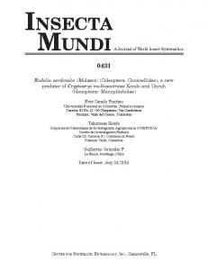
RESULTS Erosion Rates Five sites on Horse Island marsh and one site on Marsh Island were surveyed over a three-year period to determine yearly shoreline erosion rates. On a yearly basis, erosion rates ranged from 9 ± 4 cm/yr at site E to 52 ± 4 cm/yr at site D (Figure 6). The greatest average rate of erosion, over the entire three-year period, was 43 ± 4 cm/yr on Marsh Island while site C reveals the lowest average rate at 14 ± 4 ern/yr. Along the Horse Island marsh shoreline, a pattern is revealed for the erosion rates. Sites A, B, D, and E all have relatively high rates of erosion the first survey year, lower rates the second year, and then higher rates the third year (Figure 6). The overall average rate of erosion along the Horse Island marsh shoreline was 24 ± 4 ern/yr . The surveyed positions of the shorelines at each site are illustrated in Figure 7.
Styles of Erosion Figure 8 illustrates the three different shoreline responses observed during marsh erosion: (1) cleft and neck formation,
Journal of Coastal Research, Vol. 17, No. 3, 2001
Schwimm er,
676
(2) neck cut-off, and (3) undercutting with rootm at toppl ing . Clefts are formed when erosion cuts a V-shaped notch into a relatively linear stretch of shoreline . When two clefts form adja cent to one anothe r , the portion of the shoreline in between th e cleft s is referred to as a ma rsh neck. These necks were observ ed to reach three meters in length. Many stretches of shoreline in the study area exhibit an undulatory geometry of alternating clefts and necks (Figure 9). At sites A and th e northern portion of site B, and to a lesser extent site C (Figu re 7), clefts eroded at a faster rate than th e adjacent necks . Thi s changed th e shoreline geometry from a relatively linear stretch to a series of alternating clefts and necks . At sites D, E, and the southern portion of site B, this cleft-neckcleft geometry was alre ady established at th e start of th e survey and was pr esumably sustained by a un iform erosion rate along th e shoreline length. At sites A, B, D, and E, individual marsh necks eroded as much as two meters per year while sites A, B, and E show similar rates of erosion in th e formation of clefts (Figure 7). Marsh necks can also be eroded at th eir base faste r than at th e tip of the neck creating an hour-glass or pinched appearanc e (Figures Sa and 10). Eventually, erosion will separate the neck from th e shoreline leaving only a small marsh stack (Figures Sa and 11). This isolated portion of marsh is then rapidly eroded away .
REHOBOTH
HORSE
34/17/19 cm/yr
ISLAND
BAY
30/20/28 cm/yr
15/13/13 cm/yr
42/16/52 cm/yr
MARSH
Q'SLAND 47/49/33 cm/yr
MARSH
o
400m
Fig ure 6. Avera ged yea rly erosion r at es for th e six surveyed sites over a th ree-year period . Estimate d er ror for ea ch erosion rate is ± 4 em/yr.
SITE A SITES
0=-0J METERS
•
1
MruR'S ~
AVERAGE EROSI ON RATE = 23 cm/yr AV ERAGE EROSION RATE
SITEC 02
AVERAGE EROSION RATE = 14 cm/yr
= 26 cm/y r SITEE
SITE MARSH ISLAND
o 2' "MET'E'R'S
o
2
'METE'RS
AVERAGE EROSION RATE = 37 cm/yr
AVERAGE EROSION RATE = 19 cm/yr
AVERAGE EROSION RATE = 43 cm/yr
Figu re 7. The cha nge in surveye d shore line positions for each site over a th ree-year period.
J ournal of Coast al Research, Vol. 17, No.3, 2001
Marsh Shorelin e Eros ion
a)
'
STACK
PINCHED NECK
677
,
,'
~
..IL
0
2m
(PLAN VIEW )
..IL
..IL
I
ROOTMAT HOLE
b) 2.00
(CROSS-SECTION) ..IL
I
..IL
..IL
1.75
..IL
z
a
..IL
..IL
..IL
..IL
i=
..IL ..IL
>
W
~
W W
..IL
>
a::
..IL
..IL
..IL ..IL
..IL
i=
:3w
..IL
..IL
1.50
..IL
..IL
«
..IL ..IL
1.25
I..IL I ..IL
..IL I -I
ROOTMAT
..IL ..IL ..IL
MUDD Y PEAT
• SURVEY POINT
..IL
..IL ..IL
1.00 1
2
3
4
5
DISTANCE (m)
Figur e 8. a ) Cartoon sketch of t he main fea tures developed a long a marsh shore line due to wave eros ion. b) Cross-section of a marsh overhan g from surveyed da ta illu st ratin g the relati onsh ip bet ween the mar sh rootm at a nd th e und erl ying mud s. MTL = estimated mean tide level. Figure 9. An exa mple of cleft and neck shoreline developme nt . Note the met er st ick for sca le.
Due to th e exposure of th e shore line scarp and th e erodibility of the underlying muds, wa ve action undercut s th e rootmat forming a marsh overhan g (Figu res 3 and Sb). Th e rootmat, with it s intertwining network of root s accompanied by a mass of ribb ed mu scles on th e surface, is remarkabl y rigid , forming overhangs up to 50 em in length. Under cuttin g enlarges th e overhang until it br eaks off and toppl es into the bay . Ten sional crack s can develop on th e marsh surface as toppl ing begin s (Figure 8b). Thi s sty le of erosion is refer red to as beam failure and h as al so been obse rved on riv er banks (P IZZUTO, 1984). Toppled portions of th e rootm at are commonly obser ved in th e water at th e base of th e scarp. Thi s undercutting-toppling process was obser ved on both lin ear st re tches of shoreline as well as on marsh necks. As th e waves hit th e shoreline underneath an overha ng , th e water is forced upward against th e rootmat. Thi s upw ard movement of water can produce a hole through the marsh surface th at erod es th e sediment lea vin g only a network of grass root s (Figu re Sa). Thi s process was obser ved alon g lin ear stre tches of shorelin e and at th e a pex of cleft s and hast en s erosion as th e marsh is now bein g eroded from two dir ections.
Erosion Rate Predictions Th e calcula ted wave power for eac h of the nine long-t erm erosio n sites (Figu re 4) is listed in Tabl e 1. Th e ave rage erosion ra te for eac h site was the n plotted agains t the estimate d wave power (Figu re 12). A positive corre lation betw een th ese two varia bles is a ppa re nt wit h the calcul ated regression equation: R = 0.35pl.I
(1 )
wh er e R is erosion rate (m/yr) and P is wave power (kW/m) (adjus te d r 2 = 0.80, sta nda rd error = 0.27 log units, significan ce F = 0.000 7). Th e three Rehoboth Bay sites (1, 2, 3) plot with the lowest wave power s and erosion rates. Th e two Delaware River sites (6 and 7) plot slightly higher for both varia bles . Th e four Delaware Bay sites (4, 5, 8, 9) plot with th e greatest rates of eros ion an d wave power s. Overall, as th e amount of wave power that reaches a marsh shoreline increases, the shoreline erosion rate also increases.
Jo urnal of Coastal Resear ch, Vol. 17, No. 3, 2001
Schwimmer
678
Figure 10. A marsh neck exhibiting a pinched appearance due to wave erosion.
DISCUSSION Erosion Rates Surveying shorelines over short distances and time periods presents some interesting problems when trying to interpret erosion rates. The shoreline is commonly undercut by wave action causing the marsh rootmat to form an overhang. This marsh overhang continues to develop until it breaks off and topples into the bay . Consequently, there are two processes of erosion associated with a marsh shoreline. The first is relatively more continuous as the underlying mud is eroded by waves breaking against the shoreline. The second is episodic as the overhang breaks away from the marsh. As long-term shoreline erosion rates are usually determined from aerial photographs and presented in plan view, it is the erosion rate that is related to the retreat of the marsh surface (i.e., rootmat) that is of primary significance when estimating erosion rates. Surveying the shoreline over short time intervals (six months or less), can result in significantly different erosion rates depending on the relative timing of the survey and of the toppling events. Once the marsh overhang reaches a threshold, toppling most likely occurs over a span of only a few days or perhaps in only one day as the result of a storm event (WRAYet al., 1995). As a result, surveying a stretch of shoreline over a period that includes a toppling event will produce relatively large yearly erosion rates. On the other hand, surveys conducted just after a toppling event and be-
fore the next may result in relatively low yearly erosion rates. It is therefore important to compare short-term average erosion rates to longer-term average erosion rates to access the significance of the short-term surveys. SWISHER (1982) documented erosion rates in Rehoboth Bay over a 43-year time period (1938-1981) using aerial photographs. The average erosion rate for the southern portion of Horse Island marsh (equivalent to the stretch between sites Band E in this study) was calculated to be about 23 cm/yr and for Marsh Island about 50 crn/yr (SWISHER, 1982). Over a three-year period, average erosion rates from this study are 23 ::!:: 4 cm/yr and 43 ::!:: 4 crn/yr for these two areas, respectively. The similarity of these rates either means that average erosion rates from a three-year survey can be used as a proxy for long-term erosion rates or that it is a mere coincidence that these rates are so similar. Until additional surveys are conducted to understand the short-term natural variations of shoreline erosion rates, I will assume that the similarity is an interesting coincidence. Four of the five survey sites along the Horse Island marsh shoreline (sites A, B, D, E) exhibit a similar variation in erosion rates over the three-year span (Figure 6). From the first year to the second year, a decrease in erosion rates occurs and then the rates increase from the second year to the third year. This would suggest that the total amount of wave power striking the shoreline at each site also varied in a similar manner. This line of reasoning can be extended to one of the controlling variables of wave power, such as wind speed. If
Journal of Coastal Research, Vol. 17, No.3 , 2001
679
Ma rsh Sho re line Erosion
Figure 11. A marsh stac k formed by th e se pa ration of a marsh neck from the shoreline.
th ere were ext end ed periods of strong winds, during storms for example, throughout a particular year, th is would produce a greater frequency of relatively high wave hei ghts. Thi s in turn would generate gre ater wav e powers, which th eor etic al ly would produce higher erosion rates. RAMSEY et al. (1998) tabulated th e number of storm events that produced tid es greater than seven feet a bove MLLW (mean lower low water ) at Breakwater Harbor (see Figure 4 for location). In 1996, three such storm events occurred , in 1997 only one storm, and in 1998 ther e wer e again three
storm events . Thi s storm activity corr elates well with th e variation s in erosion rates and suggests that storm events are strongly ass ocia te d with shorelin e erosion. KAMPHUIS (1987 ) al so showed that storms are a primary factor in the erosion of glacia l till bluffs. Th er efore , over time periods of a year or so, marsh shoreline erosion rates are highly variable as they are , in part, related to th e frequency and magnitude of storm events .
10 - . - - - --
Tabl e 1. Long -term erosion rate and wave power data for individual sites. See Fig ure 4 for site locations. Average Erosion Rate'
Wave Power
Site
(rn/y r)
(k W /m)
1 2 3 4 5 6 7 8 9
0.17 0.23 0.50 4 .50 7.30 0.77 1.10 6.12 1.96
0.66 0.75 0.78 6.48 7.43 3.01 5.12 8.77 9.21
, Associated t ime peri ods a nd sou rces of erosion da ta : Sites 1, 2, 3 = 1938-1981 (SWISHER, 1982) Sites 4, 5 = 1842-1977 (FHENcH, 1990 ) an d 1843-1 956 (Maur rneyer , 1978) Site s 6, 7, 8, 9 = 1940-1978 (PHILLIPS, 1985)
- - - --
-
-
-
-
-
-
-
-
-
-
-
-
---,
•
R = 0.35 p "
• 5 •8
Adju sted r 2= 0 .80
4
•9 •6
•3 •1
•7
•2
0.1 -j-----,---..---,----,--r-r-.-r--,--0.1
• Marsh Erosion Site --''-,---.---,--,-,..,-,-rI 10
Wave Power (P) (kW/m)
Figu re 12. lines.
Erosion ra t e vs. wave power for nin e selected marsh shore-
J ourn al of Coas ta l Resea rch , Vol. 17, No.3, 2001
Schwimmer
680
"STRAIGHT" SHORELINE
CLEFT AND NECK FORMATION
UNDERCUTTING AND ROOTMAT TOPPLING
NECK CUT-OFF
Figure 13. A possible cyclic process of marsh shoreline erosion.
Styles of Marsh Shoreline Erosion Three styles of shoreline erosion were observed in the study area: (1) cleft and neck formation, (2) neck cut-off, and (3) undercutting and rootmat toppling. Although data obtained from this study do not provide a quantitative relationship among these styles a qualitative relationship can be proposed. The shoreline geometry over relatively short distances (e.g., ten meters), is controlled by lateral variations in erosion rates. Because the lithology of the scarp sediment is consistent along the marsh shoreline, it is likely that erosion rates are influenced by the interaction of waves with the nearshore bathymetry and the shoreline. As the geometry of the shoreline changes, the nature of this interaction also changes thereby altering the constructive and destructive wave interference patterns. Consequently, the foci of wave erosion along the shoreline also changes. This interactive relationship can be illustrated through the changing styles of erosion. Figure 13 presents a possible cyclical process of marsh shoreline erosion in Rehoboth Bay. Starting with a relatively straight or linear shoreline, the process of erosion can change this initial geometry to one that is undulatory, consisting of clefts and necks. The marsh necks can then be eroded quickly, through undercutting and toppling, or be cut off at the base. In either case, the shoreline geometry is changed back to a more linear shape (Figure 13). A linear shoreline can also retain this geometry through undercutting and toppling along its length. If these zones of higher erosion rates (e.g., apex of clefts, tip and base of necks) are designated by the interaction of waves with the nearshore bathymetry and the shoreline, then these areas will change location as the shoreline geometry changes. Clefts, for example, are formed by relatively rapid erosion rates. However, clefts are usually limited to three meters in depth within the study area. Why are deeper clefts not found and why did the erosive process slow down? Perhaps as the cleft developed, a threshold was reached where the erosive force is attenuated due to the depth and narrow geometry of the cleft. As the adjacent marsh necks continue to erode, the depth of the cleft becomes smaller which may allow erosion rates in the cleft to increase to a level similar to that of the necks. The alternating cleft-neck geometry may then be maintained as the shoreline retreats. Alternatively, the marsh neck could be undercut or cut off which would rees-
tablish a more linear shoreline, potentially allowing the process to begin again. Overall, there is a potential feedback mechanism that occurs as the shoreline geometry changes due to erosion which alters the variables that direct the erosive forces that in turn change the shoreline geometry. Besides wave action, other factors may playa role in shoreline erosion. In Rehoboth Bay, SWISHER (1982) observed ice sheets in the nearshore zone and on the marsh surface up to one meter from the shoreline. After the ice broke up, large sections of the marsh surface were found up to five meters inland from the shoreline. SWISHER (1982) attributed this redistribution to ice rafting and observed that the ice had sheared off the rootmat from the underlying mud. During the time of this investigation, however, ice sheets were not observed in the nearshore zone. Boat wakes may also cause shoreline erosion. Although power boats can be common in Rehoboth Bay, they are only frequent during the late spring to early fall months. While conducting field work, boats were rarely observed traveling close enough to Marsh Island and at high enough speeds to produce waves that reach the shoreline. The water between Marsh Island and Horse Island marsh is relatively shallow which limits the size and speed of the boats in this area especially during low tides when the shoreline is more susceptible to wave erosion. ZABAWA and OSTROM (1980) examined the role of boat wakes on shoreline erosion in Chesapeake Bay. They concluded that boat wakes ranked third behind storm-driven waves and wind waves in causing shoreline erosion. In addition, ZABAWA and OSTROM (1980) suggested that the type of shoreline plays an important role for the potential of erosion. Shorelines made of sand and gravel, for example, are more easily eroded than marsh shorelines with their tightly-bound rootmats. Overall, their data suggest that boat wakes have an insignificant effect on marsh shoreline erosion (ZABAWA and OTROM, 1980). Biogenic activity, however, may enhance shoreline erosion (WRAYet al., 1995). Fiddler crab burrows were observed in the erosional scarp during low tide. These burrows occur throughout the scarp from just below the rootmat to the base of the scarp. The burrows may promote erosion by trapping air as waves strike against the scarp. The compressed air increases the shock pressure of the wave which, coupled with the sudden expansion of the air as the wave recedes, may intensify the erosive process. TRENHAILE (1987) considered air compression to be a very effective process of erosion on rocky coasts, although one that is not well understood.
The Shoreline Geometry of Horse Island Marsh Over a much larger distance, lateral variations in erosion rates most likely do not account for the general configuration of the Horse Island marsh shoreline as shown in Figure 2. There is a spatial- and temporal-scale problem. It seems unlikely that erosion rates measured over a ten-meter stretch of shoreline determined over three years can explain the general geometry of a one-kilometer stretch of shoreline that developed over the past 200 years (SCHWIMMER and PIZZUTO, 2000). One variable that may have an influence on shoreline
Journal of Coastal Research, Vol. 17, No.3, 2001
Marsh Shoreline Erosion
o
~
UPLANDS
400 m
I
REHOBOTH
BAY
681
grown farther out into the bay as they were simply following the mean high water contour line . Therefore, the general shoreline geometry developed as a result of the antecedent topography controlling salt marsh growth and not because of lateral variation in erosion rates.
Mechanism of Marsh Shoreline Erosion MARSH ISLAND
~ \ 400 \
\
Figure 14. The relationship between depth to the antecedent surface (measured in centimeters from the marsh surface) and the shoreline geometry.
geometry that has not been accounted for is the depth to th e antecedent topography. The antecedent topography is comprised of the Pleistocene Omar Formation (RAMSEY and SCHENCK. 1990), a fine to coarse sand with some gravel, that underlies the marsh deposits and forms the surface over which transgression occurs. The general configuration of the Horse Island marsh shoreline from north to south consists of a headland from just north of Horse Island to just south of site B, an embayment at site C, and another smaller headland at site D (Figure 2). A second embayment is located just south of site E. Here, however, the shoreline is a sandy beach and not a marsh shoreline. Figure 14 illustrates the relationship between depth to the antecedent topography and shoreline geometry. The two headlands are located in areas where the antecedent surface is relatively shallow while the embayment is found in an area where the antecedent surface is relatively deep . Furthermore, the existence of Marsh Island is also significant as it is situated where the antecedent surface is also relatively shallow. This shoreline geometry suggests a causal relationship between depth to the antecedent surface and shoreline configuration over relatively large distances. As Horse Island marsh developed, rising relative sea level first encroached the paleo-stream valleys (where the antecedent surface is relatively deep) thus restricting the initial growth of salt marsh. As relative sea level rose, transgression moved across the interfluves creating additional areas of salt marsh growth (CHRZASTOWSKl, 1986). The marsh deposits found at the lowest elevations are indeed much older than those found associated with an antecedent topographic high (SCHWIMMER and PIZZUTO, 2000) . The early-formed marsh may therefore have experienced a longer duration of shoreline eros ion compared to the later-formed marsh. In addition, it is likely that the vegetation ofthe younger marsh deposits would have initially
In Rehoboth Bay, wave attack creates a vertical scarp and commonly undercuts the rootmat forming an overhang which eventually topples into the bay . This process has also been observed in Massachusetts (REDFIELD, 1972), in Chesapeake Bay (COULOMBE, 1986; FINKELSTEIN and HARDAWAY, 1988; DOWNS et al., 1994; WRAY et al., 1995), in Delaware Bay (PHILLIPS, 1986b), and in Great Britain (ALLEN, 1989), suggesting that an erosional scarp is a common feature of retreating shorelines. In order to better understand the erosion process it is necessary to first ask the question, "What is the mech anism that promotes wave erosion?" The history of Horse Island marsh, as well as other marshes in southeastern Delaware, contain a period of marsh expansion as the shoreline prograded over lagoonal mud flats (SCHWIMMER and PIZZUTO, 2000) . During progradation, the waves presumably did not erode the shoreline and yet relative sea level was still rising and waves were undoubtedly still being generated by winds and storm events. This expansion phase ended about 200 years ago and was followed by the modern-day transgressive phase accompanied by rapid shoreline erosion (SCHWIMMER and PIZZUTO, 2000) . So why did the waves not erode the shoreline during marsh expansion and why are waves eroding the shoreline today? Previous studies have suggested that the present-day erosion of marsh shorelines is due to the recent rapid rate of local relative sea-level rise (PHILLIPS, 1986b; FINKELSTEINand HARDAWAY, 1988; KRAFT et al., 1992; DOWNS et al., 1994; WRAY et al., 1995). The rate of local relative sea-level rise in Delaware is 0.33 cm/yr (KRAFT et al., 1992). These studies, however, did not present a causal relationship between increased rates of local relative sea-level rise and shoreline erosion. FINKELSTEIN and HARDAWAY (1988) did hypothesize that the recent rapid rise of relative sea level created a deeper estuary with larger fetches . Consequently, larger waves were produced resulting in shoreline erosion. WRAY et al. (1995 ) coupled a lack of sediment input and sediment composition with rapid local relative sea-level rise as the cause of shoreline erosion. However, neither of these studies presented a detailed model illustrating how these variables are interrelated nor a mechanism that could account for alternating periods of erosion and progradation. A possible model to explain why the shoreline is eroding is presented by SCHWIMMER and PIZZUTO (2000) . This shoreline response model is based on the relative rates oflocal sea-level rise, marsh aggradation, and sed imentation in the nearshore lagoonal area. This model proposes that if the rate of relative sea-level rise is faster than the rate of nearshore lagoonal sedimentation, then the water depth will increase which in turn promotes an increase in wave height and celerity. As wave heights increase, the amount of wave power impinging
Journal of Coastal Resear ch, Vol. 17, No. 3, 2001
Schwimmer
682
on the shoreline also increases. The increased wave power causes erosion of the shoreline forming a shoreline scarp. According to this model, the mechanism that governs marsh shoreline erosion is the relative combination of the rate of local sea-level rise and the rate of sedimentation in the nearshore lagoonal area (the marsh aggradation rate is assumed to keep up with the rate of relative sea-level rise or the marsh will simply drown). The nearshore sedimentation rate is in turn influenced by sediment supply and wave energy. This mechanism allows for a more thorough understanding of the cause of marsh shoreline recession or expansion and also provides clues to paleo-environmental changes that are associated with marsh stratigraphic regressive and transgressive sequences.
Erosion Rate Predictions Variations in fetch and in water depth influence the estimated wave powers. The Rehoboth Bay sites (1, 2, 3), which are associated with the smallest fetches and shallowest water depths of the nine sites, plot with the smallest estimated wave powers (Figure 12). Sites 6 and 7 are located in the Delaware River where available fetches and water depths are potentially greater than in Rehoboth Bay but smaller than in Delaware Bay. These sites plot with greater wave powers and therefore potentially greater erosion rates than the Rehoboth Bay sites. The four Delaware Bay sites (4, 5, 8, 9) plot with the greatest potential wave powers and erosion rates. Sites 4, 5, 8, all plot close to one another most likely due to similar fetches, water depths, and orientation of the shoreline relative to the bay. Site 9 also exhibits a large wave power due to larger fetches and potentially deeper water in the lower and wider portion of the bay. Site 9, however, exhibits a lower erosion rate perhaps due to the orientation of the shoreline in relation to the bay. The shoreline is facing northwest toward Egg Island Point and across a shallow embayment (Figure 4) which greatly reduces the available fetch and water depth which in turn reduces the potential wave power for those waves approaching normal to the shoreline. Overall, the positive correlation illustrated in Figure 12 suggests that as wave power increases at one site or from site to site, the associated erosion rate will also increase. The regression equation obtained from this relationship, R
=
(2)
O.35pl.l,
is similar to that found by KAMPHUIS (1987),
(3) for the erosion of glacial till bluffs along the north shore of Lake Erie. In addition, KAMPHUIS (1987) presented a reanalysis of GELINAS and QUIGLEY'S (1973) erosion data from the same area of Lake Erie and obtained a regression equation of R
=
1.16p1.31.
(4)
In both cases, the exponent is slightly higher compared to equation (2) suggesting that marsh shorelines are more resistant to wave erosion than glacial bluffs. This correlation may be used as a predictive tool to estimate erosion rates for marsh shorelines in the Delaware Bay
region. Presumably this method could be used elsewhere provided the necessary data are available.
CONCLUSIONS 1) The primary process that causes marsh shoreline erosion in Rehoboth Bay, Delaware, is attack by wind waves. 2) Over a three-year period, the average rate of shoreline erosion along Horse Island marsh was 24 ± 4 ern/yr. On Marsh Island, the average rate of shoreline erosion was 43 ± 4 ern/yr. 3) Three styles of marsh shoreline erosion were observed in the study area: (1) cleft and neck formation, (2) neck cutoff, and (3) undercutting with rootmat toppling. Over relatively short distances (e.g., ten meters), a possible feedback mechanism between these styles may account for changes in the shoreline geometry over time. 4) Over relative larger distances (e.g., several hundred meters), the configuration of the Horse Island marsh shoreline is controlled by the antecedent topography, which governs salt marsh evolution, and not by the laterally variable rate of shoreline erosion due to wave attack. 5) A positive correlation is revealed when erosion rates are plotted vs. wave powers for selected marsh shorelines. As wave power increases, the rate of erosion increases. This correlation may be used as a predictive tool to estimate shoreline erosion rates for other fringing lagoonal marshes.
ACKNOWLEDGEMENTS I gratefully acknowledge the guidance and enthusiasm that Jim Pizzuto provided throughout this project. Support was provided by the Department of Geology at the University of Delaware. I give special thanks to Bill Chadwick, Julia Daly, Jane Reed, Will Parcel, and Nora Gelperin for all of their assistance in the field. I would also like to thank the State of Delaware Department of Natural Resources and Environmental Control, Division of Parks and Recreation, for access to Marsh Island.
LITERATURE CITED ALLEN, J.R.L., 1989. Evolution of salt-marsh cliffs in muddy and sandy systems: A qualitative comparison of British west-coast estuaries. Earth Surface Processes and Landforms, 14, 85-92. CHRZASTOWSKI, M.J., 1986. Stratigraphy and geologic history of a Holocene lagoon: Rehoboth Bay and Indian River Bay, Delaware. Ph.D. dissertation, University of Delaware, Newark, 337p. COULOMBE, B.D., 1986. Shore erosion and coastal processes along the eastern shore of Chesapeake Bay, Maryland. M.S. thesis, University of Delaware, Newark, 132p. CROWELL, M.; LEATHERMAN, S.P., and BUCKLEY, M.K., 1991. Historical shoreline change: Error analysis and mapping accuracy. Journal of Coastal Research, 7, 839-852. DALRYMPLE, R.A.; BIGGS, R.B.; DEAN, R.G., and WANG, H., 1986. Bluff recession rates in Chesapeake Bay. Journal of Waterway, Port, Coastal and Ocean Engineering, 112, 164-168. DOWNS, L.L.; NICHOLLS, R.J.; LEATHERMAN, S.P., and HAUTZENRODER, J., 1994. Historic Evolution of a marsh island: Bloodsworth Island, Maryland. Journal of Coastal Research, 10, 1031-1044. FINKELSTEIN, K. and HARDAWAY, C.S., 1988. Late Holocene sedimentation and erosion of estuarine fringing marshes, York River, Virginia. Journal of Coastal Research, 4, 447-456. FRENCH, G.T., 1990. Historical shoreline changes in response to en-
Journal of Coastal Research, Vol. 17, No.3, 2001
Marsh Shoreline Erosion vironmental conditions in west Delaware Bay. M.S. thesis, University of Maryland College Park, 240p. GALGANO, F.A., 1989. Shoreline recession and nearshore response: The Atlantic coast of Delaware, 1845-1987. M.S. thesis, University of Maryland, College Park, 161p. GELINAS, P.J. and QUIGLEY, R.M., 1973. The influence of geology on erosion rates along the north shore of Lake Erie. Proceedings 16th Conference of Great Lake Research, 421-430. HARDISKY, M.A. and KLEMAS, V., 1983. Tidal wetlands natural and human-made changes from 1973 to 1979 in Delaware: Mapping techniques and results. Environmental Management, 7, 339-344. HEQUETTE, A. and Ruz, M-H., 1991. Spit and barrier island migration in the southeastern Canadian Beaufort Sea. Journal of Coastal Research, 7, 677-698. HOUGHTON, J., 1997. Global warming: The complete briefing. New York: Cambridge University Press (2nd edition), 251p. INTERGOVERNMENTAL PANEL ON CLIMATE CHANGE, 1995. Climate Change 1995: The science of climate change. Contributions of Working Group I to the Second Assessment of the Intergovernmental Panel on Climate Change, Houghton, J.T., Meira Filho, L.G., Callender B.A., Harris, N., Kattenberg, A., and Maskell, K., eds., Cambridge University Press, UK, 572p. KAMPHUIS, J.W., 1987. Recession rate of glacial till bluffs. Journal of Waterway, Port, Coastal and Ocean Engineering, 113, 60-73. KEARNEY, M.S. and STEVENSON, J.C., 1991. Island land loss and marsh vertical accretion rate evidence for historical sea-level changes in Chesapeake Bay. Journal of Coastal Research, 7,403415. KRAFT, J.C.; YI, H.I., and KHALEQUZZAMAN, M., 1992. Geologic and human factors in the decline of the tidal salt marsh lithosome: The Delaware estuary and Atlantic coastal zone. Sedimentary Geology, 80, 233-246. MAURMEYER, E.M., 1978. Geomorphology and evolution of transgressive estuarine washover barriers along the western shore of Delaware Bay. Ph.D. dissertation, University of Delaware, Newark, 274p. PHILLIPS, J.D., 1985. A spatial analysis of shoreline erosion, Delaware Bay, New Jersey. Ph.D. dissertation, Rutgers University, New Brunswick, 194p. PHILLIPS, J.D., 1986a. A spatial analysis of shoreline erosion, Delaware Bay, New Jersey. Annals of the Association of American Geographers, 76, 50-62. PHILLIPS, J.D., 1986b. Coastal submergence and marsh fringe erosion. Journal of Coastal Research, 2, 427-436. PIZZUTO, J.E., 1984. Bank erodibility of shallow sandbed streams. Earth Surface Processes and Landforms, 9, 113-124. RAMSEY, K.W.; LEATHERS, D.J.; WELLS, D.V., and TALLEY, J.H., 1998.
683
A summary report of the coastal storms of January 27-29 and February 4-6, 1998, Delaware and Maryland. Delaware Geological Survey, Open File Report No. 40, University of Delaware, Newark, 43p. RAMSEY, K.W. and SCHENCK, W.S., 1990. Geologic map of southern Delaware. Delaware Geological Survey, Open File Report No. 32, University of Delaware, Newark. REDFIELD, A.C., 1972. Development of a New England salt marsh. Ecological Monographs, 42,201-237. ROSEN, P.S., 1977. Increasing shoreline erosion rates with decreasing tidal range in the Virginia Chesapeake Bay. Chesapeake Science, 18, 383-386. ROSEN, P.S., 1980. Erosion susceptibility of the Virginia Chesapeake shoreline. Marine Geology, 34, 45-59. SCHWIMMER, R.A. and PIZZUTO, J.E., 2000. A model for the evolution of marsh shorelines. Journal of Sedimentary Research, 70, 10261035. SPOERl, R.K.; ZABAWA, C.F., and COULOMBE, B., 1985. Statistical modeling of historic shore erosion rates on the Chesapeake Bay in Maryland. Environmental Geology and Water Sciences, 7,171-187. SUNAMURA, T., 1992. Geomorphology of Rocky Coasts. New York: John Wiley & Sons, 302p. SWISHER, M., 1982. The rates and causes of coastal erosion around a transgressive coastal lagoon, Rehoboth Bay, Delaware. M.S. thesis, University of Delaware, Newark, 210p. TITUS, J.G. and NARAYANAN, V.K., 1995. The probability of sea level rise. U.S. Environmental Protection Agency, No. EPA230-R-95008, Washington D.C., 186p. TRENHAILE, A.S., 1987. The geomorphology of rock coasts. Oxford: Clarendon Press, 384p. U.S. ARMY, CORPS OF ENGINEERS, 1984. Shore Protection Manual (4th ed.), U.S. Government Printing Office, Washington, D.C. WIGLEY, T.M.L. and RAPER, S.C.B., 1992. Implications for climate and sea level of revised IPCC emissions scenarios. Nature, 357, 293-300. WILCOCK, P.R.; MILLER, D.S.; SHEA, R.H., and KERHIN, R.T., 1998. Frequency of effective wave activity and the recession of coastal bluffs, Calvert Cliffs, Maryland. Journal of Coastal Research, 14, 256-268. WRAY, R.D.; LEATHERMAN, S.P., and NICHOLLS, R.J., 1995. Historic and future land loss for upland and marsh islands in the Chesapeake Bay, Maryland, U.S.A.. Journal of Coastal Research, 11, 11951203. ZABAWA, C. and OSTROM, C. (eds.), 1980. Final report on the role of boat wakes in shore erosion in Anne Arundel County, Maryland. Coastal Resources Division, Maryland DNR, Annapolis, MD., 239p.
Journal of Coastal Research, Vol. 17, No.3, 2001