Ubiquitous Digital Imaging Systems James Cross*, Chris Baber, Sandra I. Woolley School of Electronic & Electrical Engineering, University of Birmingham, Birmingham, B15 2TT UK ABSTRACT In this paper we will describe the design, construction and application of a wearable digital imaging project based on the PC/104 embedded PC board [1]. The systems for image capture, manipulation and communication will be presented and power-consumption, heat dissipation and user-interface design will be considered. The paper will also discuss the results of an archaeological field trial and demonstrate the potential of image sequence tagging methods for efficient data retrieval in documentary applications. The compact, robust PC/104 system was originally designed for embedded systems applications but is fully compatible with standard PC systems. The use of a standard platform removes many compatibility problems enabling the use of standard software and hence simplifying the communication of information between users and, importantly, enabling cost-effective development and usage. An archaeological field trial: For archaeologists the goal is to determine as much as possible from a working site, unfortunately, this can only be achieved by destructive excavation. Documentation of the excavation is best achieved with photography, however, as with many documentary applications, one could usefully take thousands of photographs which then need to be carefully catalogued themselves. Our paper will discuss the results of a user field trial using a wearable PC/104 image capture system and demonstrates the potential of image sequence tagging methods for efficient data retrieval in documentary applications. Keywords: Wearable, PC/104, digital imaging, document retrieval, archaeology, EMC
1. WEARABLE IMAGE COMPUTING People are carrying and using an increasing array of personal electronics such as mobile phones, PDAs (Personal Digital Assistants) etc. Many digital imaging systems are impractical for mobile use because of their size. Those that are small enough for everyday mobile use, such as digital cameras, often have limited storage and processing capability. Already people carry their laptops, but they are not really mobile so much as portable. They cannot be used successfully or safely on the move. With the announcement of G3 [2] (3rd Generation Mobile Specification), many companies announced small handheld devices, which can be used for video and voice communications. What is clear is that there are many applications would benefit from considerable computing power on the move with emphasis in particular on video and imaging. At the University of Birmingham UK, we have been working on a prototype imaging device that can address these issues. By creating a wearable PC based on standard PC architecture, significant gains can be made in terms of reduced hardware and software development time, and the ability to run standard software. The PC/104 specification [1] has been used for some time, and in that time it has been used mainly in embedded applications, such as car assembly lines and other complex process monitoring applications. They are based around standard PC architectures so are 100% compatible, yet their form factor is about the same as a 3½” floppy disk. This means that all ports are available and access to expansion connectors mean that upgrades are as easy as with a standard PC. Modern PC/104 boards employ all the modern ports such as USB (Universal Serial Bus), IrDA (Infrared Data Association) and flat panel interfaces. Traditionally embedded systems are used in arduous conditions, both atmospheric (temperature and contaminants) and mechanical (vibration and shock). In addition they are very low power and in most cases only require a single 5V supply, which is easy to produce from batteries, as opposed to a desktop’s multiple supplies that are difficult to produce from a mobile source. Wearable devices, for example ‘Startle CAM’ [3], WetPC [4] and VASE laboratory’s ROME [5] system. Previous applications of PC104 to wearable computers have tended to capitalise on their inherent ability to stack boards. From an ergonomic point of view, stacking could produce cumbersome products. *
Correspondence: email:
[email protected]; WWW: http://Wear-IT.Net; telephone: +44 121 414 7521; fax: +44 121 414 4291
Sensors and Camera Systems for Scientific, Industrial, and Digital Photography Applications II, Morley M. Blouke, John Canosa, Nitin Sampat, Editors, Proceedings of SPIE Vol. 4306 (2001) © 2001 SPIE · 0277-786X/01/$15.00
425
1.1 The Wearable Imaging PC Specification
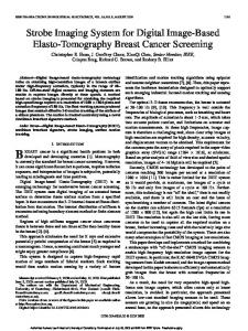
Figure 1 The Wearable Imaging PC, battery, camera (left) and Head Mounted Display Module (Right)
The imaging PC was designed and built using a PC/104 module housed in an aluminium box containing all the necessary connectors together with the Hard Disk Drive (HDD). Power regulation is handled by a separate unit, and a purpose -built battery pack has been developed to allow comfortable wearing on the waist.
Processor RAM Graphics Video Input Storage Power Interfaces
266MHz 1.8V Low Power Pentium 64MB SODIMM 2MB VRAM C&T 69000 SAA7111A 6.5GB IBM Travelstar™ UDMA33 Mobile Hard Disk Single supply 5V @ 1A (running) (5W) Video VGA Analogue 36bit TFT Flat Panel Interface1 Composite Video Input 75 Ohm NTSC/PAL Legacy 2x RS232 COM Ports Parallel Port1 Floppy Disk 1 UDMA IDE HDD Interfaces 10-Base-T Network Port USB Port IrDA Serial Port1
Table 1 A Summary of the Wearable Imaging PC Specifications 1
Not required for the wearable imaging PC, but easily accessible for future modifications
426
Proc. SPIE Vol. 4306
1.2 Energy Management Traditionally mobile devices such as laptops have battery lives in the region of two to three hours. With a ubiquitous system one would typically want the life to be closer to a working day. Therefore eight hours was chosen as target point for the design. For laptops the display alone can require as much as 5W (Watts). With the wearable PC, the PC/104 requires about 5W, and in addition to this the HDD requires a further 1W. This means that the long term running requirement is at least 6W. On system startup the power requirements are much higher as the system initializes and the HDD spins up to its operating region. The power requirements were up to 15W for short periods (3 Amps). Fortunately there are advantages too, where using power management the requirements can be reduced substantially such as powering down all devices when not required such as the HDD, and processor throttling during idle times. Such a variable load offered a challenge for the design of a reliable Power Supply Unit (PSU). For a practical system the PSU must be as efficient as possible, which means a switching supply is required. Off-the-shelf components proved to be both expensive and troublesome. Many off-the-shelf DC-DC converters have difficulty responding to the current variability the wearable, often over or undershooting the 5V required to run the wearable. Current Consumption at Power On 3.5
3
Current A
2.5
2
Operating system boot
1.5
1
System Startup HDD spin up
Memory Testing
0.5
0 0.00
Time (Sec) 0.20
0.40
0.60
0.80
1.00
1.20
1.40
Figure 2 Typical Power Supply Current Variability
Fortunately, there are DC-DC converters where the response is under the control of the designer and at significant cost, weight and size savings. The National Semiconductors Simple Switcher™ [I] offers a range of devices that can be configured at low cost and component count. Using the 260kHz LM2676 the PSU exceeded the specification required by the PC/104 board providing rise times, and regulation well within the specification. Further, the PSU was tested to five Amps (25W) still performing within specified margins. Finally the PSU was then considered robust enough for the rigors of wearable computing. The final design consisted of double-sided surface mount technology similar size to a postage stamp. The efficiency of the PSU exceeds 90%, offering approximately 8 hours from our chosen battery, which is acceptable. Heat dissipation can be a major problem in the field of mobile devices. Laptop users will appreciate that a standard laptop, when used for a few hours appears to be very hot indeed; both the power supply and the laptop itself feel hot to the touch. For it to be hot to the touch the surface, usually constructed from plastics, would be in the region of >40 Deg C. This means that the internal workings would be much hotter. For mobile devices, it is not desirable to run a fan because this further increases the power required to run the system – the use of heat sinks and spreaders are more the norm. For wearable devices however, the form factor of the overall design leads to some difficulties in maximizing the surface area, whilst in a laptop the form actor is governed by the size of the integral display. Our first prototy pe wearable PC - ‘WearCAM’, had an aluminum case, which served several purposes in that it;
Proc. SPIE Vol. 4306
427
Figure 3 The PC/104 housed in the aluminium case (cover removed). •
Assisted heat dissipation.
•
Provided RF Screening provides reduction in both emissions and susceptibility associated with EMC [6].
•
Protected the device from electrostatic discharge that would result in failure.
•
Offers limited resistance to shock, vibration and other mechanical abuse.
The core of PC/104 board is the CPU and the graphics chipset, which are integrated into a single MCM (Multi Chip Module)[II]. The MCM is where the clock speeds are highest, and therefore the most heat is produced. The design of the board allows the MCM to be bonded to a single aluminum heat sink, which provides adequate cooling without forced air.
428
Proc. SPIE Vol. 4306
Figure 4 A Thermal Analysis of the Uncovered System Figure 4 shows the results of a thermal analysis of the wearable with the cover removed whilst running the processor intensive task of data compression. The image taken with a thermal imaging camera, does not tell the whole story because varying emissivity of the components means some surfaces appear hotter because they emit radiation more effectively than others. Heat sinks surfaces appear hottest even when they are the same temperature as the surroundings. Still the core appeared to be operating at a dangerously high temperature, both at risk of failure and injury to users. A thermocouple measured the actual temperature to be approximately 64 Deg C and agrees with the thermal contour graph.
Figure 5 A Thermal Analysis of the Covered System
Proc. SPIE Vol. 4306
429
With the unit fully enclosed, the cover is heated to about 30 Deg C at full power. This results in a surface that is warm but not hot to touch. This increase in area significantly aids the cooling of the internal electronics. The device was configured to run Microsoft Windows 98™ SE, which enabled the use of ACPI [6] (Advanced Configuration and Power Interface) support, the successor to plug and play and advanced power management. Immediately a reduction in the power consumed by the device was evident and the current reduced from 1A down to 0.7A. In addition, software called ‘Rain’ was installed attempts to run a processor ‘HALT’ (low power mode) process as and idle process, often used by the ‘over-clocking community’ by those who deliberately run processors at elevated clock speeds for increased performance. This reduced the current further to 0.5A while the device is idle – i.e. not running any tasks. This also has the effect of significantly reducing the temperature of the core to a very cool 31 Deg C at 21 Deg C ambient, simply because a system running Windows 98 is idle perhaps 80% of the time. In summary, for a ubiquitous computer based system, it is not acceptable to have high power requirements because this leads to undesirable properties such as heavier batteries and waste heat, which can cause the user discomfort. The prototype wearable computer described here still managed to produce high temperatures, even though it is a relatively low power device, purely by virtue of the fact that there is limited space/area for heat dissipation. However, with efficient designs for power supplies and good support for power management on modern PC/104 boards it has been possible to reduce the power consumption and heat dissipation by at least 50%.
1.3 Application The ‘WearCAM’ is still at the prototyping stage and uses an analog composite video input for capture from CCD devices. It is anticipated that very high-resolution capture will be possible by direct interface to the system bus. Analog capture has significant limitations in the size and spatial accuracy, but at the same time it does allow video to be transmitted via a single wire without the need for compression at full frame rate for video capture. For this purpose, software was specifically written that allows easy capture, either automatically (on a timed basis) or by the intervention of the user. The images files are compressed using JPEG compression and stored with a filename denoting the time the image was taken. The software was written with the wearability aspect in mind. This means the user may not be able to see the software clearly and might want to use a small keypad with limited functions such as [up/down/select/menu/adjust] allo wing the images to be captured and stored without the need for a keyboard and mouse, which clearly are not appropriate for wearable use. For test purposes the ‘WearCAM’ has been used in a variety of situations, including studies on the effects of wearable computer systems on the users attention whilst performing other tasks [12]. Pictures were taken in various tests around the University campus.
2.0 FIELD ARCHAEOLOGICAL CASE STUDY, FORUM NOVUM, ITALY The Forum Novum field archaeological trial provided a number of interesting challenges to a wearable system similar to the WearCAM. The original prototype system was configured to take a picture every 20 seconds without any user intervention. The original system requires no interface in this configuration, but the Head Mounted Display (HMD) could be added quickly if required. The site at Forum Novum provided an ideal opportunity to test the device in a real situation. It was hoped that the field trial would help answer the following;
430
•
Will it work in the high temperatures and dusty environments?
•
Does the device impede the user?
•
How would the user make use of the images?
•
What information do the archaeologists wish to gain from it?
•
What changes need to be made to this system in order to fulfill their needs?
Proc. SPIE Vol. 4306
Figure 6 The system in use (Pictured: Dr Vince Gaffney) Birmingham University Field Archaeology Unit (BUFAU)
The ‘WearCAM’ was configured to take pictures every 20 seconds throughout the day. This allows one to follow the movements of the wearer, and allows us to test the device in harsh conditions. Clearly, this does not offer the archaeologist a great deal of assistance at this stage, and later developments depend heavily on whether the basic wearable system is appropriate to field archaeology.
Figure 7 WearCAM Pictures Forum Novum, Italy (Selected from over 1000)
2.1 Results The selection of pictures in the figure 7, show that the device functioned on the site and produced useful material. Since pictures were taken every 20 seconds, we have a complete record of the events from the point that the unit was activated to the point at which it was deactivated. Even with the relatively low resolution of the captured images, it is possible to determine the site boundaries and even capture high detail on the site. The images are better than expected from the small CMOS camera (See Figure 2). From the pictures it is possible to determine where the picture was taken, at what time and it is also possible to see the site changing with time. This is useful for field archaeology since, unfortunately, learning about the site is only possible by destruction of the site.
Proc. SPIE Vol. 4306
431
2.2 User Feedback We received many useful suggestions for improvements. The belt used for the device was approved; it was found that the WearCAM’s weight is not an issue when worn around the waist and the total weight of the belt including battery and PC is just over 2Kg (4½lbs) with approximately even weight distribution [ 9]. The idea of the battery on one side and the computer on the other, works well to balance the load. The main problem encountered was the lack of feedback from the device. For future trials, we will use the Head Mounted Display (HMD) to provide user feedback. The main problem with the HUD is that it has been shown to cause significant distraction, interfering with the users normal conduct [ 11, 12. The particular device that is used on WearCAM covers one eye, and it is not transparent. Research has shown that simply wearing a video camera can be beneficial, e.g., users can view the recording after performing a task and discuss the images. However, it was felt that some form of viewfinder is still necessary for this application. Typically, for the images to be of maximum benefit they must contain more information. Currently the images are stored as separate files that are indexed by the time and date. The need for the image to be tagged with other information such as its location e.g. using GPS, direction in which the picture was taken and other textual information would be of great benefit. Other novel extensions to the system are possible with existing hardware, for example, geological-rectification is a function which the device could perform in real-time. This involves a picture of the ground that is then perspective corrected in order to product a birds-eye-view of the ground. The image resolution is key here, since there needs to be a high enough resolution for detail in the background to be captured since when the image is processed this will appear the same depth as information from the foreground. So far image capture has been achieved using a small CMOS imaging device connected to the analog video-in. A more direct capture system based on a high-resolution CCD image sensor would be more versatile, allowing fast capture at different resolutions. 2.3 Archaeological Field Trial Summary The wearable imaging system has many applications, including, but not limited to, the field archaeology application. As with off-the-shelf wearable systems, the WearCAM can provide a significant amount of processing power that can be worn about the body, however, more research needs to be conducted into interfacing with this type of system. Computers have come a long way in a relatively short time but wearable systems will continue to be of limited use, until an interface is developed that allows better unobtrusive interaction. The images collected in the field trial show that the system worked well in the field, and they offer a good account of the archaeologist’s movements and actions during the day, which can then be viewed later. To enhance the usefulness of these images, they could be tagged, using voice or textual information that would then enable the user to search more easily. If the site had multiple users, wireless communication of the images and text could prove a real benefit and this is the focus of more research.
3.0 FURTHER WORK The development of the original wearable device allows the user to have much more than a digital camera can offer. Convergence, it seems, is not just limited to household information appliances, but also to personal technologies to. Whilst the ‘WearCAM’ can provide the user with a complete desktop system that can be worn, issues still remain meaning that it is of limited use. At the moment the ‘WearCAM’ can already provide the user with very advanced imaging capabilities on the move, such as delivering live pictures as a sort or wearable web-cam using a GSM phone. The plan at this stage is not only to take advantage of the device to produce very high quality and resolution images, but also a means to make the sequence of images much more meaningful allowing them to be tagged. ACKNOWLEDGEMENTS Windows and Windows 98 SE are trademarks of the Microsoft Corporation; CT(69000), Pentium™ are trademarks of the Intel Corporation USA. The PC/104 board used in this trial is the Microspace MSM-P5S from Digital Logic AG (Ltd) http://www.digitallogic.ch The author(s) wish to express their sincere thanks to Dr. Vince Gaffney and Dr Sally Exon of BAFAU, and to Dr. Helen Patterson of the British School of Rome for their support in the field trials in Italy.
432
Proc. SPIE Vol. 4306
http://www.bufau.bham.ac.uk/newsite/staff/gaffnevl.html (Dr Vince Gaffney) http://www.bufau.bham.ac.uk/newsite/projects/forum_novum/Default.htm (The Forum http://www.bufau.bham.ac.uk/newsite/home.htm (BUFAU),
Novum Project)
Special thanks to Mike Hiller, Miles Industrial Electronics (UK) http://www.milesie.co.uk for the help and support with the PC/104 technologies. REFERENCES
I. II.
1
PC/104 Specification V2.3 June 1996 – The PC/104 Consortium
2
Wireless Application Protocol (WAP) and new network standards such as Third Generation (3G). http://www.mobileipworld.com/wp/whitepaper.html
3
Healey, J. and Picard, R. StartleCAM: a cybernetic wearable camera, Proceedings of the 2 nd International Symposium, Wearable Computers, LOS Alamitos, CA: IEEE, 1998, 42-49 - http://www-white.media.mit.edu/tech-reports/TR-468/
4
WetPC – Technical background and specifications, for an submersible wearable PC http://www.wetpc.com.au/public/techback.htm
5
VASE Laboratory HOWTO: Build your own VASE Lab Wearable http://wearables.essex.ac.uk/spec/wear-construction.html
6
EMC – Electromagnetic Compatibility, a website dedicated to EMC http://www.tu-harburg.de/et1/Emc/main.html
7
ACPI - The Advanced Configuration and Power Interface (ACPI) specification. Phoenix Technologies Ltd http://www.phoenix.com/platform/acpi.html
8
Baber, C., Haniff, D., Cooper, L., Knight, J. and Mellor , B.A., Preliminary investigations into the human factors of wearable computers, In H, Johnson, L. Nigay and C. Roast (eds) People and Computers XIII Berlin: Springer-Verlag, 313-326, 1998 http://www.bham.ac.uk/ManMechEng/IEG/hci98a.html
9
Baber, C., Knight, J., Haniff, D. and Cooper, L. The Ergonomics of Wearable Computers, Mobile Networks and Applications, 4, 1999 pp. 15-21 http://www.bham.ac.uk/ManMechEng/IEG/monet.html
10
Cross, J. Baber, C. Woolley, S., Wearing Computers - An Archaeological Case Study, IEE Colloquium on Wearable Computing, November 2000
11
Sampson, J.B. Cognitive performance of individuals using a head mounted display while walking, Proceedings of the Human Factors and Ergonomics Society 37th Annual Meeting, Santa Monica, CA: Human Factors and Ergonomics Society, 338-342, 199312
12
Baber, C., Sutherland, A., Cross, J. and Woolley, S.I., A wearable surveillance syst em: implications for human memory and performance, 3rd. International Conference on Engineering Psychology & Cognitive Ergonomics, Edinburgh, November, 2000
National Semiconductor http://www.national.com Simple Switcher LM2676 Specification http://www.national.com/pf/LM/LM2676.html Microspace low power Smartcore http://www.digitallogic.ch/english/products/datasheets/smartmodule.asp
Proc. SPIE Vol. 4306
433