IEEE Transactions on Ultrasonics, Ferroelectrics, and Frequency Control ,
vol. 56, no. 11,
November
2009
2553
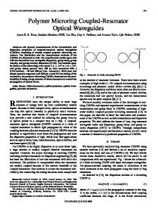
Ultra-Miniature Coupled Resonator Filter with Single-Layer Acoustic Coupler Tiberiu Jamneala, Uli B. Koelle, Alexandre Shirakawa, Stephen R. Gilbert, Phil Nikkel, Chris Feng, and Rich Ruby Abstract—Coupled resonator filters designed using a singlelayer coupler require coupling materials with an acoustic impedance less than 5.0 MRayl. Carbon-doped oxide, with an acoustic impedance of 4.8 MRayl and an acoustic attenuation of 200 to 600 dB/cm at 1 GHz, can be used as a single-layer coupler to produce a competitive 2-stage coupled resonator filter for cellular handset applications in the gigahertz frequency range. The electrical response of our filter is superior to that of coupled resonator filters using a traditional acoustic mirror as the coupling element. We present an ultra-miniature 0.58 mm × 0.38 mm coupled resonator filter operating at a frequency of 2.15 GHz.
I. Introduction
T
he increasing complexity of modern cellular handsets requires a constant effort toward size and cost reduction for all of their components. Among such components, the microwave filters at the antenna front end are facing price erosion while their electrical performance must not be compromised. Microwave filters fabricated using the film bulk acoustic resonator (FBAR) technology are desired for their low in-band insertion losses, which are due to the high quality factors of the FBAR resonators [1]–[3]. The cost of these filters is dominated by the size of their die, which has shrunk dramatically in recent years thanks to design innovation and process optimization. However, as this technology slowly matures, the age of rapid size reduction is likely over. Based on FBAR technology, the coupled resonator filter (CRF) technology replaces single FBAR resonators with vertically stacked pairs of resonators, each pair being joined together (coupled) by an acoustic coupler. The stacking of the resonators provides, among other benefits, very significant die size reduction, enabling further advances in component miniaturization. Though not discussed here, it is also worth mentioning that the other 2 major benefits of the CRF technology are the capability to provide single-to-balanced signal conversion and impedance transformation, neither of which is available within standard FBAR technology. We have earlier demonstrated that CRF resonators can be fabricated with a single-layer nonconductive coupler [4], [5], provided that materials with low acoustic impedance and otherwise acceptable acoustic properties can be found. This single-layer coupler approach successfully deManuscript received January 9, 2009; accepted August 20, 2009. The authors are with Avago Technologies, Inc., San Jose, CA (e-mail:
[email protected]). Digital Object Identifier 10.1109/TUFFC.2009.1342 0885–3010/$25.00
parts from the traditional use of an acoustic mirror as a coupling element [6]–[8], not only because it is simpler to fabricate but also because it reduces the undesired effects of the mirror, such as the spurious resonances [9], [10]. Even when metals with high acoustic impedance (like tungsten or molybdenum) are used for the filter electrodes, a sufficiently large acoustic impedance discontinuity between the electrodes and the coupler can only be achieved if the coupler acoustic impedance is smaller than about 5 MRayl [4]. This constraint severely limits the choices for the coupler material to plastics, resins, and highly doped oxides, materials with high acoustic attenuation, often substantially greater than 200 dB/cm at 1 GHz. Such high attenuation values strongly affect the filter response by degrading the insertion loss, and hence it becomes necessary to balance the requirement for small acoustic impedance with the requirement for small acoustic attenuation. In this paper, we present first a comparative analysis of one-stage CRF filters fabricated with Dow Chemical’s Silicon Low k dielectric resin (SiLK) (Dow Chemical Company, Midland, MI) and with carbon-doped oxide (CDO) as coupler layer materials. The CDO films are deposited by plasma-enhanced chemical vapor deposition using an industry-standard process tool. We show that the typical acoustic impedance and attenuation of our CDO coupler material [11], [12] provide a superior solution for the CRF filters when compared with SiLK material, even though CDO has higher acoustic impedance than SiLK. Some material properties of the coupler layer (like density and thickness) are determined through direct measurements. Other properties (like the acoustic impedance and attenuation) are determined through model fits to the fabricated filters’ measurements for which sufficient constraints exist [4]. Single-stage CRF filters have mainly a theoretical importance because of the slow roll-off of their frequency response. Practical CRF filter topologies for microwave applications usually start with 2-stage topologies. However, multiple-stage filters have much increased insertion losses, mostly due to the high acoustic attenuation of the coupler. Using CDO as the coupler material, we demonstrate the fabrication of a competitive ultra-miniature 2-stage CRF filter with a 4.8% bandwidth operating at a frequency of 2.15 GHz. II. Acoustic Properties of the Coupler The diagram of a one-stage CRF filter with a singlelayer acoustic coupler is shown in Fig. 1. As in the case
© 2009 IEEE
2554
IEEE Transactions on Ultrasonics, Ferroelectrics, and Frequency Control ,
vol. 56, no. 11,
November
2009
Fig. 1. Diagram of a single-stage coupled resonator filter with single-layer acoustic coupler.
of FBAR filters, this CRF filter sits on top of an air cavity etched in the base silicon wafer. The base wafer is hermetically sealed by a capping wafer to ensure ideal acoustic boundary conditions at the 2 air interfaces. The piezoelectric material is AlN, and the electrodes are made of either molybdenum or tungsten. The coupler material is sandwiched between electrodes 2 and 3, which need to provide a large acoustic impedance discontinuity for the coupler. Because the coupler is nonconductive, the CRF filter has galvanic isolation between input (electrode 1) and output (electrode 4). The relevant material properties of any coupler material are the acoustic impedance and the acoustic attenuation, and hence a choice of coupler material becomes a choice of these 2 properties. For a chosen coupler material, the coupling strength between the 2 resonators in the filter can be optimized by varying the coupler thickness. If the coupling is too strong, a filter with a wide bandwidth and pronounced mid-band sag is produced. If the coupling is too weak, the filter bandwidth is too narrow and the filter cannot meet the bandwidth requirements. Microwave filters for cellular handsets typically require a 4% bandwidth with respect to their operating frequency, which represents a relatively small degree of coupling. It can be demonstrated that, depending upon the material of electrodes 2 and 3, only coupler materials with acoustic impedance smaller than a maximum value Zmax can be used to produce a desired filter response (i.e., a desired passband or coupling) [4]. Zmax is significantly smaller than the electrode acoustic impedance to produce a small 4% coupling. For tungsten (acoustic impedance 102 MRayl), Zmax is about 5.0 MRayl; for molybdenum (acoustic impedance 63 MRayl), Zmax is reduced proportionally to about 3.1 MRayl. As stated in the introduction, there are relatively few materials with acoustic impedances below 5.0 MRayl, materials that are often avoided for microwave applications due to their high acoustic losses. Nevertheless, we must select among these materials to fabricate a CRF filter with a single-layer coupler.
Fig. 2. Measured S-parameters of one-stage CRF filter with CDO (thick traces) and SiLK (thin traces). The top plot is the transmission S-parameter and the bottom plot is the reflection S-parameter.
TABLE I. Acoustic Properties and Layer Thicknesses of the Materials in the CRF Stack. Material AlN Mo W CDO SiLK
Thickness (A)
Velocity (m/s)
Impedance (MRayl)
9000 3500 2100 4100 1500
11 040 6230 5316 3400 1944
35.8 63.5 102.6 4.8 2.2
III. One-Stage CRF Filter: SiLK vs. CDO Fig. 2 shows the on-wafer measured S-parameters of a one-stage CRF filter with CDO coupler and tungsten electrodes (thick traces) and one of a filter with SiLK coupler with molybdenum electrodes (thin traces), respectively. Table I shows the relevant acoustic properties of the materials used in the fabrication of these filters. The 50 Ohm port measurement was performed with calibrated 150-µm pitch air-coplanar Cascade Microtech (Cascade Microtech, Beaverton, OR) probes. Our earlier work [4], [5] concentrated on filters fabricated using SiLK dielectric resin. Despite having an acoustic impedance of only 2.2 MRayl, suitable for both molybdenum and tungsten electrodes, SiLK possesses an extremely large acoustic attenuation of about 2100 dB/cm at 1 GHz. This produces filters with a pronounced tilt in the passband response (Fig. 2, thin trace). As is often the case with materials rarely used for microwave applications, the acoustic properties, especially the acoustic attenuation values at high
jamneala et al.: ultra-miniature coupled resonator filter with single-layer acoustic coupler
Fig. 3. Model simulation of one-stage CRF filter with increasing acoustic attenuation values from 500 dB/cm (thin trace), 1500 dB/cm (middle trace), and 2500 dB/cm (thick trace).
frequencies, are not initially known. It is then difficult to predict which materials will perform well until the filters have been fabricated. We obtained these values through fits to the filter measurements using a complex Mason model modified to describe lossy materials [4]. The high acoustic attenuation of SiLK is possibly due to the more disorganized structure of this material, which impedes the scatter-free propagation of acoustic phonons. In Fig. 3, we show a model simulation of the one-stage CRF filter for 3 values of acoustic attenuation of the coupler material: 500 dB/cm, 1500 dB/cm, and 2500 dB/cm. One can note the passband deformation for large attenuation values, with the right side of the passband being much more affected. This has a simple intuitive explanation, because the coupler is subject to larger mechanical stress for frequencies near the high-frequency side of the passband and thus the attenuation plays a more important role. Therefore, it is clear that the largest difference between the SiLK and CDO filters should be found at the high-frequency end of the filter passband, as is shown in the measurements of Fig. 2. Other, smaller differences between SiLK and CDO CRF filters can be explained by the relative difference in electrical conductivity between thin molybdenum and tungsten or by frequency mismatch between the bottom and top resonators. In addition to the ultra-high attenuation, the spin-on SiLK also proved a difficult material due to nonconformal deposition across the resonator area, which resulted in a thinner coupler layer at the resonator’s edge. The effect of SiLK thinning at the edge of the resonator is modeled in Fig. 4, with the assumption of 100-Ǻ SiLK thinning for 2% of the resonator area at the edge of the resonator (1–2 microns for a 10,000 μm2 area). The indentation at the high-frequency end of the passband can be reproduced as seen in the measurements of Fig. 2. The indentation is due to perturbed coupling between the pair of resonators as a consequence of the thinner coupler material. The frequency location and the size of the indentation can be used to extract the amount of thinning as well as the areal extension of this effect.
2555
Fig. 4. Modeling the effect of SiLK nonconformal deposition in the CRF filter passband.
At the high end of the acceptable acoustic impedance range, carbon-doped oxide materials [11] offer the benefit of a stiffer structure less prone to phonon scattering and hence the promise of a smaller acoustic attenuation. In addition, the conformal step coverage provided by the chemical vapor deposition technique used to deposit CDO should produce better coupler thickness uniformity across the resonators. Indeed, we found that the acoustic attenuation of this type of CDO material is in the range of 200 to 600 dB/cm at 1 GHz, which is much smaller than the acoustic attenuation of SiLK. The benefit of the smaller attenuation is weighed against the larger acoustic impedance (4.8 MRayl). Only tungsten electrodes 2 and 3 are compatible with CDO if a flat filter passband is desired. Because higher acoustic impedance is almost always associated with a higher acoustic velocity (i.e., thicker material is needed to produce a desired phase change), the optimum coupler thicknesses are 4100 Ǻ for CDO and 1500 Ǻ for SiLK. The measured results in Fig. 2 demonstrate the superior performance of the CDO coupler material compared with SiLK. Especially for the high-frequency side of the filter passband, the insertion loss improvement can be as high as 0.5 dB for the one-stage filter. The significantly lower acoustic attenuation of the CDO produces an almost symmetric, tilt-free passband with no sign of coupler edgethinning caused by nonconformal deposition. The greatest benefit of CDO is the low acoustic attenuation, which is even more apparent for multiple-stage CRF filters. IV. 2-Stage CRF Filter with CDO Coupler Unlike FBAR filters, CRF filters have a slow roll-off of their electrical response near the passband, independent of the resonator quality factor. Typical near-band rejection specs for most microwave filters are virtually impossible to meet with a one-stage CRF filter due to the insufficiently fast roll-off this topology can provide. Hence, it becomes clear that practical CRF filters must be, at the minimum, 2-stage filters. However, the increase in the number of filter stages also increases the filter insertion loss. Due to
2556
IEEE Transactions on Ultrasonics, Ferroelectrics, and Frequency Control ,
vol. 56, no. 11,
November
2009
Fig. 6. Transmission S-parameter (measurement) of a 2-stage CRF filter with CDO coupler. Fig. 5. Layout of the 0.58 mm × 0.38 mm 2-stage CRF filter.
the lower acoustic attenuation of the CDO, demonstrated above for the one-stage filter, the fabrication of multiplestage CRF filters can now be contemplated. Based on our optimized simulation results, we have fabricated an ultra-miniature 2-stage CRF filter with a singlelayer CDO coupler and a total size of 0.58 mm × 0.38 mm (Fig. 5). We have used 8100 Ǻ AlN as the piezoelectric material and 2100 Ǻ tungsten for the electrodes of each resonator in the coupled pair. The 2 filter stages have identical stack thicknesses and similar areas (~13,000 µm2), and the resonant frequency of the FBAR resonators is 2.15 GHz. The acoustic impedance of the 4100-Ǻ CDO coupler is 4.8 MRayl, and the acoustic attenuation is in the range of 200 to 600 dB/cm at 1 GHz. The layout of this 2-stage filter is shown in Fig. 5, including the bondable pads on the capping wafer. The ground pads at the input and output of the filter are separated to maintain good filter rejection in the likely case of a nonideal ground connection through a finite inductance. One can note that the active resonator area is only a small fraction of the total die area (0.23 mm × 0.23 mm), while the rest is occupied by pads, sawing street, and the seal-ring required for the hermetic sealing of the filter using our microcap process. The resonators have a squashed polygon (“apodized”) shape typical of FBAR resonators to increase the mean free path and smooth out the parasitic lateral modes [13]. The calibrated, on-wafer transmission S-parameter measurement of the 2-stage CRF filter performed with 150-µm pitch air-coplanar probes is shown in Fig. 6 for the filter passband. The filter presents insertion losses of less than 2.5 dB over approximately 103 MHz, which is almost a 4.8% bandwidth. This is much wider than what has been achieved with traditional acoustic mirror CRF filters [9], [10]. In addition, the single-layer coupler does not need to be modified to suppress lateral modes or improve wide-band performance, as is the case with the acoustic mirror devices. Modifications of the coupler from the optimum solution always cause degradation of the filter insertion loss as the coupling efficiency decreases for the fundamental signal. Though not shown here, the filter response can be further improved by adding series induc-
Fig. 7. Measured near-band rejection of a 2-stage CRF filter with singlelayer CDO coupler.
tors in the form of wirebonds, trace inductors, or surface mount components on the handset board to reduce the in-band ripple, as is common practice in the industry. The measured temperature coefficient of frequency (TCF) of this 2-stage CRF filter is −25 ppm/C at both sides of the passband. The filter’s near-band rejection is shown in Fig. 7. The rejection below 2.0 GHz is better than 50 dB, which makes this filter an excellent candidate for an UMTS-1 Rx filter with adequate rejection in UMTS-1 Tx band (1920– 1980 MHz). In other applications, where the receiveand-transmit bands are even closer in frequencies, the near-band rejection that can be achieved with a 2-stage CRF filter might not be sufficient, and several filter stages should be considered. The single-coupler suspended CRF filter also presents an outstanding performance over a wider 0.1- to 6.5-GHz frequency range (Fig. 8). The wide-band rejection is better than 40 dB up to a frequency of 6.5 GHz and better than 50 dB up to a frequency of 4.5 GHz. When compared with the wideband response of a traditional acoustic mirror filter [9], one can notice the absence of the undesired spurious resonances. The single-layer coupler produces fewer spurious resonances than the more complex coupling mirror, and the high acoustic attenuation of CDO further diminishes the remaining resonances to undetectable lev-
jamneala et al.: ultra-miniature coupled resonator filter with single-layer acoustic coupler
Fig. 8. Wide-band measurement of the transmission S-parameter of a 2-stage CRF filter with single-layer CDO coupler.
els. Although the spurious resonances of the traditional CRF filter design can be reduced by modifying the mirror [9], such changes always have a negative impact on the filter insertion loss, as was noted above. Our CRF filter with single-layer coupler does not require such modifications, and hence it presents a superior solution for typical handset applications. V. Conclusion CRF technology can provide very significant area reduction for microwave filters used in cellular handsets when compared with the more mature FBAR technology. The acoustic properties of the coupling layer are crucial for the performance of these filters. We found that CDO, despite the relative high value of the acoustic impedance (4.8 MRayl) can be successfully used as a single-layer coupler material to fabricate CRF filters with tungsten electrodes. The superior performance of CDO filters is partially due to the lower value of the acoustic attenuation (200–600 dB/cm at 1 GHz) for CDO. We have fabricated a 2-stage, ultra-miniature 0.58 mm × 0.38 mm CRF filter with a 103-MHz bandwidth at better than 2.5-dB insertion loss with excellent near-band and wide-band rejection and free of spurious resonances. The filter is operational at a frequency of 2.15 GHz.
2557
[2] T. Jamneala, P. Bradley, U. B. Koelle, and A. Chien, “Modified Mason model for bulk acoustic wave resonators,” IEEE Trans. Ultrason. Ferroelectr. Freq. Control, vol. 55, no. 9, pp. 2025–2029, Sep. 2008. [3] R. Ruby, P. Bradley, D. Clark, D. Feld, T. Jamneala, and K. Wang, “Acoustic FBAR for filters, duplexers and front end modules,” in IEEE Microwave Symp. Dig., vol. 2, Jun. 2004, pp. 931–934. [4] T. Jamneala, M. Small, R. Ruby, and J. D. Larson III, “Coupled resonator filter with single-layer acoustic coupler,” IEEE Trans. Ultrason. Ferroelectr. Freq. Control, vol. 55, no. 10, pp. 2320–2326, Oct. 2008. [5] M. Small, T. Jamneala, L. A. Callaghan, J. D. Larson III and R. C. Ruby, “A de-coupled stacked bulk acoustic resonator (DSBAR) filter with 2 dB bandwidth > 4%,” in Proc. IEEE Ultrasonics Symp., Oct. 2007, pp. 604–607. [6] K. M. Lakin, “Bulk acoustic wave coupled resonators filters,” in Proc. IEEE Frequency Control Symp., May 2002, pp. 8–14. [7] K. M. Lakin, “Coupled resonator filters,” in Proc. IEEE Ultrasonics Symp., vol. 1, Oct. 2002, pp. 901–908. [8] G. G. Fattinger, R. Aigner, and W. Nessler, “Coupled bulk acoustic wave resonator filters: Key technology for single-to-balanced RF filters,” in IEEE Microwave Symp. Dig., vol. 2, Jun. 2004, pp. 927– 929. [9] G. G. Fattinger, J. Kaitila, R. Aigner, and W. Nessler, “Single-tobalanced filters for mobile phones using coupled resonator BAW technology,” in IEEE Microwave Symp. Dig., vol. 2, Aug. 2004, pp. 416–419. [10] R. Thalhammer and R. Aigner, “Energy loss mechanisms in SMRtype BAW devices,” in IEEE Microwave Symp. Dig., Jun. 2005, pp. 225–228. [11] S. R. Gilbert, P. Nikkel, R. Ruby, T. Jamneala, and J. D. Larson, III, “Improved coupled resonator filter performance using carbondoped oxide decoupling layer,” in Proc. IEEE Ultrasonics Symp., Sep. 2009 (to be published). [12] R. Ruby, S. R. Gilbert, A. Chien, and T. Jamneala, “GPS and WiFi balanced to un-balanced CRF filters using SiOCH a de-coupling layer,” in Proc. IEEE Ultrasonics Symp., Sep. 2009 (to be published). [13] J. D. Larson, III, R. Ruby, and P. Bradley, “Bulk acoustic mode resonator with improved lateral mode suppression,” U.S. Patent 6 215 375, Apr. 2001.
Tiberiu Jamneala received his B.A. degree in physics from Boston University, Boston, MA, in 1999, and his Ph.D. degree in Physics from University of California, Berkeley, CA, in 2001. He has since been a designer of passive microwave components with Agilent Technologies/Avago Technologies, Wireless Semiconductor Division. His previous interests concentrated in the areas of fundamental electro-magnetic properties of single atoms on clean metallic surfaces, scanning tunneling spectroscopy and atomic manipulation, and ultra-high vacuum systems and low temperatures. His current professional interests include the design of FBAR/CRF filters and multiplexers, modeling of FBAR and CRF resonators, modeling of nonlinear effects in acoustic resonators and RF test and calibration.
Acknowledgments The authors wish to thank John Choy, Moshe Gat, Kevin Grannen, John D. Larson III, Donald Lee, Steven Ortiz, Mike Rhyner, and Martha Small for their contributions and support of this work. References [1] K. M. Lakin, “Thin film resonator technology,” IEEE Trans. Ultrason. Ferroelectr. Freq. Control, vol. 52, no. 5, pp. 707–716, May 2005.
Uli B. Koelle received his Hauptdiplom in Physics from University of Tuebingen, Germany, in 1996 and his Ph.D. in Materials from Arizona State University Tempe, Arizona in 1999. After his Ph.D. he joined the Fiberoptic Products Division of HP/Agilent/now Avago Technologies, working on the design and test of vertical-cavity surface emitting lasers (VCSELs). His interests include optical and acoustic high-Q resonators. He is currently an R&D Project Manager with Avago Technologies, Wireless Semiconductor Division.
2558
IEEE Transactions on Ultrasonics, Ferroelectrics, and Frequency Control ,
Alexandre A. Shirakawa was born in Curitiba, Brazil, in 1978. He received his master degree in Telecommunications from the Universidade Federal do Parana (UFPR), Brazil, in 2002 and the Ph.D. degree at the University of Bordeaux – IMS Laboratory of Microelectronics, in 2006. He joined CEA/Leti (Microelectronics Lab from CEA) at the end of 2006 as Research Engineer for the development of BAW-CRF design techniques. In the end of 2007, he joined Avago Technologies, where he is currently an FBAR NPI Product Engineer. He has authored or co-authored 32 scientific papers and he holds 5 patents in BAW filters field and their applications. His research interests are BAW filters design, modelling and integration.
Stephen R. Gilbert received his B.S. degree in materials science from Carnegie Mellon University, Pittsburgh, PA, in 1991, and his Ph.D. degree from Northwestern University, Evanston, IL, in 1996, where he studied ferroelectric and piezoelectric thin films. After his graduate work, he joined the Central Research Laboratory at Texas Instruments where he worked on the integration of ferroelectric thin films for advanced memory applications. He joined HP Labs in 1998, where his work on embedded FRAM and piezoelectric thin films continued. Dr. Gilbert is currently with the Wireless Semiconductor Division of Avago Technologies where he works on advanced FBAR filter technologies. He has given many invited presentations and holds more than 30 U.S. patents.
Phil Nikkel received his M.S. degree in physics from University of Arizona, Tucson, AZ, in 1979. Since 1979, he has been working as a semiconductor process engineer in the Wireless Semiconductor Division of Hewlett-Packard, Agilent Technologies, and Avago Technologies. Recently, he has been active in the field of coupled resonator technology and the optimization of electrical and mechanical properties of thin tungsten.
vol. 56, no. 11,
November
2009
Chris Feng received his M.S. degree in metal physics from Beijing University of Science and Technology, Beijing, China, and his Ph.D. degree in material science from Colorado School of Mines, Golden, CO. From 1995 until 2000, he worked as a process, integration, and device engineer at Motorola’s Advanced Product Research and Development Laboratory (APRDL). Since 2000, he has been with Agilent Technologies/Avago Technologies. His current primary focus is FBAR and CRF process and device development.
Rich Ruby obtained his B.S., MS., and Ph.D. degrees at the University of California, Berkeley, CA, in 1977, 1981, and 1984, respectively. His Ph.D. work was in superconductivity. After his graduate work, he joined HP Labs (later to become Agilent Labs, and now Avago Technologies) working on superconductivity, E-beam lithography, X-ray lithography, and packaging. In 1993, he started work on free standing bulk acoustic wave resonator devices (FBAR) and has stayed with that technology since. He has made many contributions to the commercialization of FBAR filters and duplexers. He was made an Agilent Fellow in 2002 and holds that title as well as director of technology at Avago. Dr. Ruby was also awarded the Barney Oliver Prize and the Bill Hewlett Award for his work on FBAR technology. Rich holds more than 50 patents in the area of FBAR devices and has given numerous invited papers. FBAR has since won several industrial awards.