May 19, 2004 -
week ending 21 MAY 2004
PHYSICA L R EVIEW LET T ERS
VOLUME 92, N UMBER 20
Ultralow Emittance, Multi-MeV Proton Beams from a Laser Virtual-Cathode Plasma Accelerator T. E. Cowan,1,9 J. Fuchs,1,2,9 H. Ruhl,1,9 A. Kemp,1,9 P. Audebert,2 M. Roth,3 R. Stephens,1 I. Barton,1 A. Blazevic,3 E. Brambrink,3 J. Cobble, 4 J. Ferna´ ndez, 4 J.-C. Gauthier,2 M. Geissel,3 M. Hegelich,4,5 J. Kaae,1 S. Karsch,5 G. P. Le Sage,6 S. Letzring, 4 M. Manclossi,7 S. Meyroneinc,8 A. Newkirk,1 H. Pe´pin,2 and N. Renard-LeGalloudec9 1
2
General Atomics, San Diego, California 92121, USA Laboratoire pour l’Utilisation des Lasers Intenses, UMR 7605, CNRS-CEA-E´ cole Polytechnique-Universite´ Paris VI, 91128 Palaiseau, France 3 Gesellschaft fu¨ r Schwerionenforschung, 64291 Darmstadt, Germany 4 Los Alamos National Laboratory, University of California, Los Alamos, New Mexico 87545, USA 5 Max-Planck-Institut fu¨ r Quantenoptik, Garching, Germany 6 Lawrence Livermore National Laboratory, University of California, Livermore, California 94550, USA 7 Laboratoire d’Optique Applique´e, ENSTA-E´cole Polytechnique, 91761 Palaiseau CEDEX, France 8 Centre de Protonthe´rapie d’Orsay, 91402 Orsay, France 9 Physics Department, MS-220, University of Nevada, Reno, Nevada 89557, USA (Received 9 November 2003; published 19 May 2004) The laminarity of high-current multi-MeV proton beams produced by irradiating thin metallic foils with ultraintense lasers has been measured. For proton energies >10 MeV, the transverse and longitudinal emittance are, respectively, 1012 V=m [11] that ionizes the surface atoms almost instantaneously, forming a �1 nm thick ion layer which, together with the electron sheath, resembles a virtual cathode (see Fig. 1). The resulting accelerated ion beam is composed mostly of protons originating primarily from contaminant layers of water vapor and hydrocarbons on the target surface [3,4]. As will be shown below, the extremely strong, transient acceleration that takes place from a cold, initially unperturbed surface, results in the low beam emittance that may be limited only by the collisions with the comoving electrons during the acceleration [12]. Such an acceleration process represents a new and potentially near-ideal kind of ion diode 204801-1
0031-9007=04=92(20)=204801(4)$22.50
PACS numbers: 29.27.Fh, 52.38.Kd, 52.40.Kh, 52.70.Nc
as compared either to the ion beams generated from plasma plumes [13], i.e., from the laser-heated turbulent plasma on the front side of the foils, or to the conventional plasma discharge ion sources used in accelerators. Attempts have been made to measure the beam emittance or source size by using projection, on a far distant Phase I: virtual cathode Al target
x′=px/pz
x →
E ∝ (kT eλ D ) u
→
x
laser
Phase II: sheath expansion Al target
x
envelope of the ion front
→
→
E ∝ ∇(n ) n
x
z
laser
x′=px/pz
Proton beamlets focused to ~200 nm (rms)
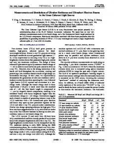
FIG. 1 (color online). Schematic of experiment. The laser pulse is focused on a foil having a modulated rear surface. Protons are first accelerated normal to the surface by the virtual cathode (VC) producing a modulation of the takeoff angle. The produced beamlets then expand with the quasineutral sheath. This adds an overall near-linear divergence to the beam initial angular modulation. Projected on a film stack far away, this results in a modulation of the dose, allowing one to image the VC stage magnified.
2004 The American Physical Society
204801-1
tive transverse ion temperature and a high degree of angle space and time-energy correlation. We have assessed the characteristics of the laseraccelerated ion beams in experiments performed using the 100 TW short-pulse laser at the Laboratoire pour l’Utilisation des Lasers Intenses (LULI), and the 30 TW Trident laser at the Los Alamos National Laboratory. The concept of the experiment is shown schematically in Fig. 1. Laser pulses of �20–30 J of 1 �m light (350 – 850 fs) were focused onto the front surface of thin foils of Au or Al (10–50 �m thick). Note that the targets can be used only once since they are destroyed during the shot. The accelerated protons are detected in multiple layers of radiochromic film (RCF) densitometry media [17]. The spatial distribution of the protons in a given RCF layer gives the angular emission pattern at a specific interval of proton energy. By carefully preparing the rear surface of the target foil, and by shaping the laser focal intensity distribution, we controlled the virtual-cathode phase of the acceleration where the electric field is normal to the ion charge layer [10,18]. For the data of Figs. 2(a) –2(c), we used optically flat aluminum foils on the rear surface of which we micromachined shallow grooves, 200 nm deep spaced 3:6 �m apart. From a quantitative analysis of the film optical densities, we measure that �1011 protons are produced in a single laser shot for energies above 4 MeV, which corresponds to an ion current of >1 kA at 1 mm from the target foil. We observe a decrease in the angular envelope of the protons with increasing proton energy, as has been observed previously [3,4]. However, using the modulation of the beam intensity impressed during the initial phase, we are able to image the proton-emitting surface and thus to measure for the first time directly the source size. By accelerating protons off nonperiodic surface structures, as illustrated in Fig. 3, we 10
angle (º)
film, of objects such as knife edges [14] or meshes [15] placed in the ion beam path. The transverse emittance was estimated to be �0:5 mm mrad [14]. However, the ion beam does not propagate ballistically close to the target and passage of the beam on the object induces chargeup that deflects the beam. Therefore the beam emittance or source size cannot be reconstructed precisely from such measurements. In this Letter, using a new technique that allows one to directly image the initial accelerating sheath and to fully reconstruct the transverse phase space, we experimentally show that, for protons of up to 10 MeV, the transverse emittance is as low as 0.004 mm mrad, i.e., 100-fold better than typical RF accelerators and at a substantially higher ion current (kA range). In addition, we show that the removal of the comoving electrons after 1 cm of beam expansion does not increase significantly the measured proton transverse emittance. This is the first demonstration of high-current laser-produced charged-particle beams with characteristics substantially superior to conventional accelerators. Also, we determine directly for the first time the size of the ion source, a crucial parameter for developments of high-resolution charged-particle radiography or ion patterned lithography. The technique we developed for imaging the accelerating sheath uses target design that allows manipulating the ion beam generation during the initial, virtualcathode phase of the acceleration by generating a stream of beamlets, within the expanding proton envelope, that can be used as fiducials of the acceleration. The laminarity of charged-particle beams is characterized by their emittance [16], which is proportional to the volume of the bounding ellipsoid of the distribution of particles in phase space. By Liouville’s theorem, the phase-space volume of a particle ensemble is conserved during nondissipative acceleration and focusing. For the transverse phase-space dimensions (here x-px for beam propagation along z), the area of the bounding phasespace ellipse equals "N , where the root-mean-square (rms) value of the ‘‘normalized emittance’’ "N , at a specific beam energy (or momentum p), is expressed as "N � �jpj=mc��hx2 ihx02 i � hxx0 i2 1=2 , where m is the ion mass, c is the velocity of light, x is the particle position within the beam envelope, and x0 � px =pz is the particles’ divergence in the x direction. At a beam waist, "N � ���x �x0 where �x and �x0 are the rms values of the beamwidth and divergence angle. For typical proton accelerators [e.g., the CERN Super Proton Synchrotron (SPS)], the emittance from the proton injector linac is �1 mm mrad (normalized rms) and up to 3.5 mm mrad within the synchrotron, with 1011 protons per bunch. The longitudinal phase space (z-pz ) is characterized by the equivalent, energy-time product of the beam envelope and a typical value, for the CERN SPS, is �0:5 eV s. The highest quality ion beams have the lowest values of transverse and longitudinal emittance, indicating a low effec204801-2
week ending 21 MAY 2004
PHYSICA L R EVIEW LET T ERS
7 MeV
3.6 µm spacing on target
9 MeV
10 MeV
5 0 -5 -10
~0.2 µm (b) equivalent width
(a) -10 -5
0
5
10
-10 -5
angle (º)
0
5
10
(c) -10 -5
0
angle (º)
5
10
angle (º)
10
angle (º)
VOLUME 92, N UMBER 20
5 0 -5 -10
(e)
(d) -10 -5
0
5
angle (º)
10
-10 -5
(f) 0
5
angle (º)
10
-10 -5
0
5
10
angle (º)
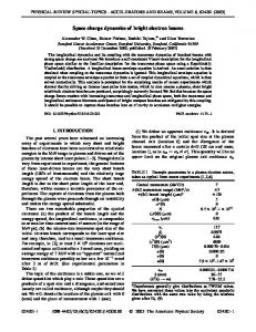
FIG. 2. (a) –(c) Angular distributions on RCF of protons accelerated from an 18 �m thick Al flat target irradiated at 1019 W=cm2 . (d) –(f) Simulated RCF images [same parameters and proton energies as in (a) –(c)] using a 3D PIC effective code.
204801-2
PHYSICA L R EVIEW LET T ERS
VOLUME 92, N UMBER 20 sub-structures on the bars
crosses
x’=px/pz
20 µm
(c)
x’=px/pz
(a)
(b)
spatial dimension on the RCF film intensity on film
x x
week ending 21 MAY 2004
(d) x
intensity on film
FIG. 3. (a) Image of a 48 �m thick Au target rear surface. (b) Resulting angular proton distribution at 8 MeV. The phasespace modulations induced by the surface structures produce corresponding intensity modulations, as illustrated in (c) for the case of the three parallel bars. Note that the modulations do not overlap; otherwise, as illustrated in (d), the proton dose between the bars would be different than the one outside, which is not the case.
verified that there is no overlap of the beam fiducials from adjacent structures that could lead to misinterpretation of the data. We establish that for protons above 4.5 MeV the decrease in the angular envelope with energy is due to a decrease of the emitting zone, but not due to a strong change in the divergence (i.e., magnification) of the beam envelope or from magnetic field deflection [2,19]. Such a decrease of the emission zone is expected for a transversally bell-shaped electron density distribution. In such a sheath, the highest energy protons are accelerated in the central, high-density portion of the sheath, whereas lower energies come from the wings of the sheath distribution and thus are emitted at a larger angle [18]. This comes from the accelerating field E � �r� � ��kThot =e��rnhot =nhot �, where nhot � exp�e��r�=kThot is the Boltzmann distribution of the hot electrons in the sheath. The measured diameter (FWHM) of the virtualcathode emission zone is of the order of 70 �m at 4.5 MeV, 45 �m at 7 MeV, and �30 �m for >9 MeV protons. In Fig. 4(a), we plot the divergence angle versus the source position of the accelerated protons by using the nanofocused structures as fiducial marks impressed in the initial beam. Note that within the central portion of the beam the phase-space correlation is almost exactly linear. This remarkable result suggests that the relativistic electron sheath has a nearly Gaussian-radial distribution in its density profile, which gives a nearly linear relation between radial position and the radial electric field in the sheath [18]. Note that this is supported by the 3D particlein-cell (PIC) simulation which displays the same behavior as shown in Fig. 4(b). By assuming that the protons in each beamlet come from an ideal line focus, we experimentally deduce an upper limit on the transverse emittance of 100 smaller than typical proton beam sources. We attribute this to the fact that during much of the acceleration the proton space charge is neutralized by the comoving hot electrons. PIC simulations show that the image generation is more complicated. Indeed, as shown in Fig. 4(b), the 204801-3
FIG. 4 (color). (a) Transverse phase space plot of the proton beam [from Figs. 2(a) –2(c)]. Error flags denote the rms angular width (1�) of the beamlets. This gives an upper limit on envelope divergence, from which we estimate an upper limit of the emittance "N at each energy, as marked (in units mm mrad). (b) Same from the effective PIC simulation 600 fs after the interaction. (c) Same as (a) but in a rotated frame. The emittance ellipses using the Twiss parameters are overlaid. The transparencies of the dots encode the value of the dose at each point, following the curves shown in (d).
observed angular width of the beamlets, which is a projection in x0 � px =pz of the transverse phase space, involves the magnitude of the initial transverse momentum oscillation (see Fig. 1) in addition to the irreducible thermal spread. Accordingly, the actual transverse emittance could be smaller than the deduced