2468
JOURNAL OF COMPUTERS, VOL. 6, NO. 11, NOVEMBER 2011
Ultrasonic Measurement System with Infrared Communication Technology Xiao Chen Department of Electronic Information Engineering , Nanjing University of Information Science and Technology, Nanjing, China Email:
[email protected]
Chenliang Wu Nanjing University of Information Science and Technology, Nanjing, China Email:
[email protected]
Abstract—In order to achieve remote control of ultrasonic measurement system, an infrared communication-based ultrasonic measurement system is developed combining wireless communication technology with ultrasonic measurement technology. The hardware circuits of entire system and the achievement of several key technologies are discussed, including transducer structure and parameters selection, design of the corresponding circuit. The system is composed of host and slave parts. The host part is composed of host microcontroller, receiver circuit, liquid crystal display circuit and infrared communication module. The slave part is composed of ultrasonic transmitter, infrared communication modules and single-chip component. The host and slave parts transmit data through the infrared communication module. AT89S52 microcontroller is used as systems main control unit and ZHX1010 infrared communication chip for wireless data transmission. The system has low-cost, the implementation of convenient, easyto-use, convenient, flexible, reliable transmission of data, and stable performance. Index Terms—infrared communication, ultrasonic, ultrasonic measurement, wireless communication, AT89S52
I. INTRODUCTION At present, the use of ultrasound characteristics for daily life of our services has played an important role. Ultrasonic measurement technology is one of physical, electronic, mechanical, and materials science-based general-purpose technologies. Ultrasonic measurement technology is through ultrasound generation, transmission and reception of the physical process completed. Its basic principle is that ultrasonic wave propagating in the medium, when encountering different interfaces, will result in reflection, refraction, diffraction, attenuation and so on. When the ultrasound propagation, amplitude,
Project 10904073 supported by National Natural Science Foundation of China. Corresponding author: Xiao Chen is with the Department of Electronic Information Engineering, Nanjing University of Information Science and Technology, Nanjing, 210044 China. Email:
[email protected]
© 2011 ACADEMY PUBLISHER doi:10.4304/jcp.6.11.2468-2475
waveform and frequency corresponding changes occur. Determination of the changes in these laws will be entitled to some of the material situation of the nature and internal structure. Ultrasound has the features such as strong directivity, nondestructive tesing, propagating a long distance in a suitable medium almost without attunation, so it is often used for distance measurements such as car reversing system [1]. When the use of ultrasonic testing, the use of single chip microcomputer (SCM) design is more convenient and in the measurement accuracy can also use up to the requirements of industrial automation. With the rapid development of science and technology, the application of ultrasonic distance measurement will become more and more widely. It will be more towards the direction of the high development of high-precision positioning to meet the growing needs of the society. The future location of the ultrasound technology will converge with intelligent automation, and ultimately the development of creative. The range finder will be a different place to play a greater role [2-4]. Computer network technology, as represented by the computer communication technology has been widely applied to various indestry fields. Single-chip microcomputer applications in many systems often use wireless communication transmission control information and data information in order to achieve the functions of remote control and measurement. As a branch of computing and communication technology, infrared communication with low-cost and simple control of the implementation, easy-to-use and transmission characteristics of high reliability, is a more common means of communication. Infrared communication as a short-range wireless communications, has been widely used in SCM [5-7]. This article first detailed infrared communication technology and the application of ultrasonic measuring technology. We develope the technology by a combination of these two self-designed a wireless data transmission system in order to transmit the data in the short-distance measured by ultrasound measurement to the host. It shows the realization of ultrasonic ranging system function of remote control.
JOURNAL OF COMPUTERS, VOL. 6, NO. 11, NOVEMBER 2011
II. PRINCIPLE AND SYSTEM Nondestructive measurement is an important means of production process in the field of modern industry to ensure product quality and performance, stability. The developed countries in the world increasing emphasis on non-destructive measurement techniques. For example, Japan's development priorities formulated in the 21st century, one of the four technology equipment life extension technology, the nondestructive measurement technique in a very important position. Ultrasonic measurement is an important nondestructive measurement techniques. As the microelectronics, computer and communication technology, ultrasonic measurement techniques developes into an advanced measurement technology, but also closely integrated multi-disciplinary high-tech product. At present, the SCM application systems are normally used cable ommunication, by the signal level conversion port RS232 or RS485 signals into direct communication is a form of wired communication systems. Cable has the advantage of relatively low error rate communications, the chances of interference is relatively small, but for lines of communication should always plug the system, the cable communications may cause to failure. At the same time, in many microcomputer application systems, often using non-electrical signals such as optical signals to send control information and data information in order to achieve remote control and telemetering functions in these applications. Currently the radio waves and microwaves have been widely used in long-range wireless communication among. However, because of shorter infrared wavelengths, the diffraction of the obstacles poor, so more suitable for applications that require short-range wireless communication of the occasion, to point a straight line to the point of data transmission.Infrared communication, as a short-distance wireless communications, in the MCU application systems have been widely applied. In this paper, we designed an ultrasonic measurement system based on infrared communication technology. The main achievement of the determination and data from the infrared wireless transmission. System includes the following sections: ultrasonic circuit, echo reception circuit, a digital display circuit, alarm circuit, infrared wireless communications circuits and single-chip microcomputer. The signal issued from single-chip microcomputer outputs after the adoption of the developed ultrasonic sensor, the use of ultrasound in the air and solid directional spread of the reflective properties, through the reception to launch its own reflection of the ultrasonic signal, according to ultrasound echo to send and receive time difference and the propagation velocity, calculated spread distance. When measurement, the sensor and the measured object is without direct contact, being able to clearly demonstrate the stability of the measurement results. III. HARDWARE
© 2011 ACADEMY PUBLISHER
2469
A. MCU Due to the design of the entire system related to data processing, real-time issues such as control, selection of microcontroller-based systems, the realization of the circuit is not only simple and low-cost, low power consumption, can greatly reduce the overall system size. Atmel microcontroller AT89S52 is selected. It is an 8bits CMOS single chip microcomputer with low power consumption and high performance. It has many functions such as special applied 16bits timing/counter, and it is compatible with standard 80C51 instruction system and 80C51 pin structure, and the chip integrates 8bits central processor and ISP Flash location and it can offer solution with high cost performance for many embedded control application systems [8,9]. B. Ultrasonic Sensor The choice of sensor in ultrasonic measurement is particularly important. Ranging in the market, many different types of sensors such as laser ranging sensors, infrared distance sensors, ultrasonic distance sensors. Laser ranging sensors and infrared distance measurement sensors are very high-precision ranging, and some test range very small. They are mostly used in precision measuring tools, leading to high prices of the sensor itself. Ultrasonic sensor is a sensor using piezoelectric effect and is commonly made of piezoelectric ceramic materials. As a result of the spread of ultrasound in the air there will be considerable attenuation, the degree of attenuation is directly proportional to the level and frequency; and high frequency of high-resolution, it should choose a short distance measuring sensor with high frequency; the measurement of long-distance application low-frequency sensors. With an ultrasonic transducer transmitting and receiving a combination of two functions, so only a pair of ultrasonic transducers alternately transmit and receive ultrasonic signals to complete the measurement requirements. The ultrasonic emission occurs when an obstacle gets reflected, the reflected wave received by the receiver. As long as the measured ultrasonic wave reflected back from the sending point to the time interval, then one can find the ultrasonic wave from the launch service to the distance between the obstacles. Piezoelectric ultrasonic transducer is the use of resonant piezoelectric crystal to work. Ultrasonic transducer within the two piezoelectric transducer chip and a board. When it's poles plus a pulse signal whose frequency is equal to the natural oscillation frequency of piezoelectric chip, the piezoelectric wafer resonance occurs, and promote the vibration of ultrasonic resonance board, when it is an ultrasonic generator; the other hand, asked if the two electrodes no applied voltage, when the board receives the ultrasonic resonance, it will be for vibration suppression of piezoelectric chip, the mechanical energy is converted to electrical signals, then it becomes ultrasonic receiver transducer. Ultrasonic emission transducer and receiver transducer is slightly different in structure, use the device on the signs should be to distinguish between.
2470
JOURNAL OF COMPUTERS, VOL. 6, NO. 11, NOVEMBER 2011
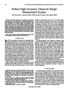
Ultrasonic sensor model selects general-purpose sensor T-40. Its paremeters is as follows. The central frequency is 40KHz. The sensitivity is 1.0mV. The insulation impadence is 100K ohm. The max input voltage is 140V. The temperature ranges from -30 to 85 centigrade degree. The max cable length is 8 meter. All data come from its manual. C. Ultrasonic Wave Transmitter Circuit Ultrasonic wave transmitter circuit provides pulse signals for the sensor. The ultrasonic wave is generated by the software generation method. P1.0 port of singlechip microcomputer outputs 40kHz square wave signal to an electrode of ultrasound transducer after reverse, and the other reverse converters via two-stage ultrasonic transducer to another electrode. In this push the form of square-wave signal will be added to the ultrasonic transducer at both ends, which can increase the emission intensity of ultrasound. Upper resistors R10 and R11 can improve the reversers 74LS04 output high drive capability [10] in Fig.1. D. Ultrasonic Wave Received Circuit The ultrasonic wave receiver circuit includes accepting detector, signal amplifier and wave transformation circuit.
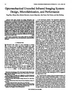
Ultrasonic receiver circuit uses IC CX20106A, the production of infrared remote control signal reception circuit by Sony Corporation of Japan, which preamplifier, automatic bias control, amplitude amplification, peak detection and shaping circuit. The infrared emission frequency IC 38KHz, ultrasound transducer is the natural frequency of 40KHz, the appropriate design of the external circuit parameters CX20106A, it can be used to receive ultrasound amplifier as shown in Figure 2. Pin 1 is CX20106A signal input terminal, pin 2 of the RC network connection for the CX20106A end, pin 3 for CX20106A detector capacitor connected client, pin 4 for CX20106A ground terminal, pin 5 for the CX20106A band-pass filter center set up end of the pin 6 capacitor connection points for the CX20106A end, pin 7 for the CX20106A signal output, pin 8 for the CX20106A power supply terminal. The transducer will receive the weak signals into acoustic vibration signals CX20106A input to the pin 1. When the received signal CX20106A, 7 pin will be a low-level output can be used to lower machine interruption of the signal source. When the slave part receives interrupt signals indicating detection of the reflected ultrasound, it turns the interrupt state machine on and started a distance-based, and results sent to the host computer [11]. E. LCD Unit The display is a typical display output device. Consider the system requirements, a display JHD162A is used. It is a character dot matrix liquid crystal display module can display a total of two lines of 32 characters, dot-matrix characters 8*5, is a very commonly used in small liquid crystal display module, in the single-chip systems, embedded man-machine interface systems have been widely used.
Figure 1. The transmitting circuit [10].
Figure 2. The receiver circuit [11].
© 2011 ACADEMY PUBLISHER
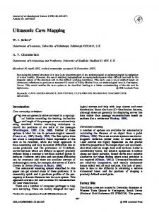
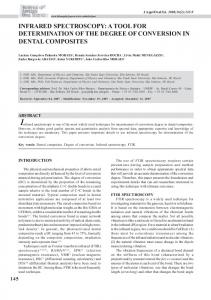
F. Infrared Wireless Communication Units In wireless communication module, ZHX1010 infrared communication module is used for data transmission. ZHX1010 is produced by ZiLOG with a larger capacity drive and low-power infrared transceiver of the SIR is very suitable for notebook computers and PDA applications. The module within the maximum speed of 1m up to 115.2Kbps. It has a wide power supply range (2.4V to 5.5V) and can be easily carried out with a variety of voltage CPU interface. ZHX1010 at 3V power supply, its a typical current of only 90uA, is ideal for battery-powered products. In addition, ZHX1010 small, only 9.9mm*3.7mm, and its external components[12]. Therefore, this system uses infrared communication ZHX1010 as the main components. Two single-chip microcomputer are used to achieve the sending and receiving data. The hareware of the host part and slave part using ZHX1010 and single-chip microcomputer are shown in Fig.3 and Fig.4 respectively. The slave microcomputer is responsible for receiving measurement data from the ultrasound measured module, and then send data through infrared to the host microcomouter. The host microcomputer receives the data and display them on the LCD screen.
JOURNAL OF COMPUTERS, VOL. 6, NO. 11, NOVEMBER 2011
Figure 3. The system hardware of host part.
Figure 4. The system hardware of slave part.
© 2011 ACADEMY PUBLISHER
2471
2472
JOURNAL OF COMPUTERS, VOL. 6, NO. 11, NOVEMBER 2011
ZHX1010 chip and single-chip microcomouter application system works as follows. First of all, the slave device can integrat ultrasonic distance measurement module, which is at the same time with a single-chip measurement and communication functions. The data can be directly obtained. Then, the data received from the machine are sent out through the ZHX1010 infrared communication chip. The host microcomputer receives the data and display them. the process works circularly [12]. The prototype of the designed host and slave hardwares is shown in Fig.5. IV. SOFTWARE Ultrasonic measurement of the process of data collection modules are as follows: the role of routine ultrasound occur by P1.0 port of SMC to send two of the ultrasonic pulse signal with pulse width of 12us and at the same time to open a counter for a time T0. Subroutine ultrasound occurred relatively simple, but accurate runtime requirements of the procedure, so the use of assembly language programming. Ultrasonic range-finder using external interrupt 0 return ultrasonic signal detection. Once the received ultrasonic signal to return, i.e., INT0 pin is low, the immediate interruption of the
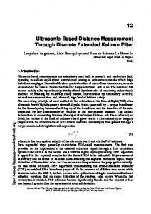
procedure to enter the ultrasonic receiver. The the software turns off the timer T0 immediately, stop the clock, and will mark the success of the word location assignment 1. If timer overflow when the return has not been detected ultrasonic signal, the T0 timer overflow interrupt 0 interrupt will be closed, and will mark the success of the word assignment ranging 2 to show the location unsuccessful. As a result of the 12MHz crystal oscillator, a counter of the number of each is 1us. When the main program from the machine detected after receiving a sign of success, the counter of the number of T0 formula-based, we can have with the location of detected objects the distance between them. The main idea of the software design will be preset, launch, receive, display and other functions compiled into a separate module, in the main program loop used in keying mode, when pressing the control key. In a certain period, followed by the implementation of each module, the main program called preset subroutine, launch subroutines, check to receive subroutine, time subroutine, and to measure the results of analysis and processing, according to the results of the decision dealing with the contents of the display program and whether the call sound alarm program. B. Software of Host Part Source code of host part includes ZHX1010 module data transfer low-level file Z1010.h with Z1010.c and top-level file M_Master.c as follows. The flow diagram of the host source code is shown in Fig.6. Z1010.c #include #include"ZHX1010.h" START
Initialize I/O﹑serial port Initialize diaplay
N BUFFER full? Y diaplay
END Figure 5. Prototype of host and slave parts.
© 2011 ACADEMY PUBLISHER
Figure 6. Flow diagram of host.
JOURNAL OF COMPUTERS, VOL. 6, NO. 11, NOVEMBER 2011
2473
ZHX1010_Send(Dat1[i]); temp1=ZHX1010_Receive(); DispCharacter(0,i,temp1);
InitSerial() void InitSerial(uint temp) { SCON=0x50; TMOD=TMOD | 0x20; TH1=(temp & 0xff00)>>8; TL1=temp & 0xff; TR1=1; }
} for(i=0;i