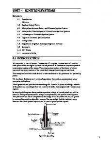
Transmission. UNIT 4 TRANSMISSION. Structure. 4.1 Introduction. Objectives.
4.2 Clutch. 4.3 Principles of Clutch. 4.4 Main Parts of a Clutch. 4.5 Types of
Clutch.
UNIT 4 TRANSMISSION
Transmission
Structure 4.1
Introduction Objectives
4.2
Clutch
4.3
Principles of Clutch
4.4
Main Parts of a Clutch
4.5
Types of Clutch
4.6
Single Plate Clutch
4.7
Multiple Clutch
4.8
Clutch Pedal Free-play Adjustment
4.9
Function of Gear Box
4.10 Types of Gear Box 4.11 Sliding Mesh Gear Box 4.12 Constant Mesh Gear Box 4.13 Gear Trains 4.14 Types of Gear Trains 4.15 Summary 4.16 Key Words 4.17 Answers to SAQs
4.1 INTRODUCTION Transmission is the mechanism which is used to transfer the power developed by engine to the wheels of an automobile. The transmission system of an automobile includes clutch, gear box, propeller shaft axle and wheels, etc. Description of various types of clutches and gear boxes has been given in the following sections of this unit. The term ‘Transmission’ is used for a device which is located between clutch and propeller shaft. It may be a gear box, an over drive or a torque converter, etc.
Objectives After studying this unit, you should be able to
understand the transmission system of automobiles,
list out the components of the transmission system,
describe the various functions and types of clutches and gear boxes, and
explain the advantages of clutches and gear box.
4.2 CLUTCH Clutch is used to engage or disengage the engine to the transmission or gear box. When the clutch is in engaged position, the engine power or rotary motion of engine crankshaft
35
Automobile Engineering
is transmitted to gear box and then to wheels. When clutch is disengaged, the engine power does not reach to gear box (and to wheels) although engine is running. Clutch is also used to allow shifting or changing of gears when vehicle is running. For shifting gears, clutch is first disengaged then gear is shifted and then clutch is engaged. Clutch has to be disengaged to stop the vehicle and also at the time of idling.
4.3 PRINCIPLE OF CLUTCH It operates on the principle of friction. When two surfaces are brought in contact and are held against each other due to friction between them, they can be used to transmit power. If one is rotated, then other also rotates. One surface is connected to engine and other to the transmission system of automobile. Thus, clutch is nothing but a combination of two friction surfaces.
4.4 MAIN PARTS OF A CLUTCH It consists of (a)
a driving member,
(b)
a driven member, and
(c)
an operating member.
Driving member has a flywheel which is mounted on the engine crankshaft. A disc is bolted to flywheel which is known as pressure plate or driving disc. The driven member is a disc called clutch plate. This plate can slide freely to and fro on the clutch shaft. The operating member consists of a pedal or lever which can be pressed to disengaged the driving and driven plate.
4.5 TYPES OF CLUTCH Some types of clutches used in vehicles are given below : (a)
Friction Clutch : It may be (i) single plate clutch, (ii) multi-plate clutch, or (iii) cone clutch. Multi-plate clutch can be either wet or dry. A wet clutch is operated in an oil batch whereas a dry clutch does not use oil.
(b)
Centrifugal clutch.
(c)
Semi-centrifugal clutch.
(d)
Hydraulic clutch.
(e)
Positive clutch.
(f)
Vacuum clutch.
(g)
Electromagnetic clutch.
4.6 SINGLE PLATE CLUTCH
36
A single plate is commonly used in cars and light vehicles. It has only one clutch plate which is mounted on the splines of the clutch shaft. A flywheel is mounted on the crankshaft of the engine. A pressure plate is connected to the flywheel through the bolts and clutch springs. It is free to slide on the clutch shaft with the movement of clutch pedal. When clutch is in engaged position, the clutch plate remains gripped between flywheel and pressure plate. Friction linings are provided on both the sides of clutch plate. On one side clutch plate is in touch with flywheel and on other side with pressure
plate. Due to friction on both sides, the clutch plate revolves with engine flywheel. Therefore, clutch transmits engine power to clutch shaft. Clutch shaft is connected to transmission (or gear box) of automobile. Thus, clutch transmits power from engine to transmission system which inturn rotates wheels of engine.
Transmission
When the clutch plate is to be disengaged, the clutch pedal is pressed. Because of this pressure plate moves back and clutch plate is disengaged from flywheel. Thus, clutch shaft stops rotating even if engine flywheel is rotating. In this position, power does not reach the wheels and vehicle also stops running. Single plate clutch is shown in Figure 4.1.
Figure 4.1 : Single Plate Clutch
4.6 MULTIPLATE CLUTCH Multi-plate clutch consists of more than one clutch plates contrary to single plate clutch which consists of only one plate. Friction surfaces are made in case of multi-plate clutch. Due to increased number of friction surfaces, a multi-plate clutch can transmit large torque. Therefore, it is used in racing cars and heavy motor vehicles witch have high engine power. The clutch plates are alternatively fitted with engine shaft and the shaft of gear box. He plates are firmly held by the force of coil springs and they assembled in a drum. One plate slides in the grooves on the flywheel and the next plate slides on spines provided on pressure plate. Thus, each alternate plate slides in grooves on the flywheel and the other on splines of pressure plate. If we take two consecutive plates, then one has inner and other has outer splines. When the clutch pedal is pressed, the pressure plate moves back against the force of coil spring, hen the clutch plates are disengaged and engine flywheel and gear box are decoupled. However, when clutch pedal is not pressed the clutch remain in engaged position and the power can be transmitted from engine flywheel to the gear box. This type of clutch has been shown in Figure 4.2.
Figure 4.2 : Multi-plate Clutch
37
Automobile Engineering
4.7 CLUTCH PEDAL FREE-PLAY ADJUSTMENT Clutch remains in engaged position when clutch pedal is not pressed. Free play adjustment is required to maintain a given free play of the pedal after the clutch is engaged. Before making this adjustment, correct floorboard clearance or clutch pedal travel must be adjusted. Floorboard clearance adjustment is made to prevent touching of floor by pedal when clutch is engaged. Clutch pedal travel adjustment is done to ensure total clutch disengagement when the clutch pedal is pressed.
SAQ 1 (a)
Describe the function of a clutch in a transmission system of an automobile.
(b)
List various types of clutches and explain the working of a single plate clutch.
(c)
How a multi-plate clutch is able to transmit more power in comparison to a single plate clutch.
4.8 FUNCTION OF GEAR BOX An automobile is able to provide varying speed and torque through its gear box. Various functions of a gear box are listed below : (a)
To provide high torque at the time of starting, vehicle acceleration, climbing up a hill.
(b)
To provide more than forward speeds by providing more than one gear ratios. In modern cars, five forward gears and reverse gear is provided. For given engine speed, higher speed can be obtained by running in higher (4th and 5th) gears.
(c)
Gear box provides a reverse gear for driving the vehicle in reverse direction.
4.9 TYPES OF GEAR BOXES (a)
Selective type gear boxes : (i)
Sliding mesh gear box
(ii)
Constant mesh gear box
(iii)
Synchromesh gear box
(b)
Progressive type gear box
(c)
Epicyclic type gear box.
4.10 SLIDING MESH GEAR BOX
38
It is simplest type of gear box out of the available gear boxes. In this type of gear box, gears are changed by sliding one gear on the other. This gear box consists of three shafts; main shaft, clutch shaft and a counter shaft. In a four speed gear box (which includes one reverse gear), the counter shaft has four gears which are rigidly connected to it. Clutch
shaft has one gear and main shaft has two gears. The two gears on the main shaft can slide in the horizontal direction along the splines of the main shaft. However, the gears on the counter shaft cannot slide. The clutch gear is rigidly fixed to the clutch shaft. It is always connected to the countershaft drive gear.
Transmission
The two gears on the main shaft can be slided by the shifter yoke by operating the shift lever (not shown in Figures). These two gears are second gear and low/reverse gear respectively. These gears can be meshed with corresponding gears on the countershaft with the help of shifter yoke and shift lever. Shift lever is operated by hand in four wheelers for changing the gears. A reverse idler gear is mounted on another (third) shaft and is always in mesh with reverse gear on countershaft. Neutral Position Figure 4.3 shows sliding mesh gear box in neutral position. In this position, the engine is in running condition, clutch remains engaged and clutch gear drives the countershaft drive gear. The direction of rotation of countershaft is opposite to that of clutch shaft. In this position Ist, IInd and IIIrd and reverse gears are free. Thus, main (transmission) shaft does not rotate and automobile wheels do not rotate. So vehicle remains stationary.
Figure 4.3 : Sliding Mesh Gear Box showing Neutral Position
First Gear When first gear position is selected by the shift lever, first gear (large gear) on the main shaft slides and is connected to first gear on the countershaft. The direction of rotation of main shaft is same as that of clutch shaft. In first gear, small gear of countershaft meshes with larger gear on main shaft, speed reduction in the ratio 3 : 1 (approximate) is obtained. Second Gear When second gear is selected by the shift lever, second gear on countershaft meshes with second gear (small gear on main shaft) on the main shaft. The direction of main shaft is same as that of clutch shaft. Speed reduction of the order of 2 : 1 is obtained in second gear. Third Gear In third gear, the main shaft is slided axially towards the clutch shaft so that main shaft is directly connected to the clutch shaft. In this position, the main shaft rotates at the speed of clutch shaft. Thus, a speed ratio of 1 : 1 is obtained. It can be noted that the clutch gear is directly connected to engine crankshaft and main shaft is connected to the wheels through propeller shaft. Reverse Gear When the shift lever is operated to engage the reverse gear, the larger (reverse) gear of the main shaft meshes with the reverse idler gear. Reverse
39
Automobile Engineering
idler gear is always connected to reverse gear on countershaft. The reverse idler gear between countershaft reverse gear and main shaft larger gear changes the direction of rotation of main shaft. Thus, the direction of main shaft becomes opposite to that of clutch shaft. Therefore, wheels of the automobile start moving in backward direction. (Note : Countershaft is also known as lay shaft.) In modern cars, there are five forward gears and reverse gear. Hence, they provide five speed ratios for forward racing and one for backward movement.
4.11 CONSTANT MESH GEAR BOX A simplified diagram of constant mesh box has been shown in Figure 14.4. In this gear box, all gears on the main transmission shaft are constantly connected to corresponding gears on countershaft or lay shaft. In addition, two dog clutches are provided on the main shaft. One dog clutch is between the second gear and cutch gear and another is between the first gear and reverse gear. Splines are out on main shaft so that all the gears are feed on it.
Figure 4.4 : Constant Mesh Gear Box
Dog clutches can also slide on main shaft and rotate with it. However, all the gears on countershaft are giddily fixed to it. Different gear ratios (speed ratios) are obtained as follows : For Three Forward and One Reverse Gear Top or 3rd speed gar is obtained when the left dog clutch is slided to left to mesh with clutch gear by using the gear shift lever. In this case, main shaft rotates at the same speed as that of clutch gear or engine crankshaft speed which is the maximum speed. Speed ratio obtained is 1 : 1. Second gear is obtained when dog cutch (left side) meshes with second gear. In this condition clutch gear rotates the drive gear on countershaft and countershaft drives the second gear on the main shaft. All other gears on main shaft are free, so they do not move. In the same manner, first gear is obtained when right hand side dog clutch meshes with first gear. Reverse gear is obtained when right side dog clutch meshes with reverse gear on main shaft. Advantage of Constant Mesh Gear Box
40
Since all the gears are in constant mesh, wear and tear of gears and any possible damage of gears do not occur in engaging and disengaging gears. Also, any sound are not generated in engaged/disengaged.
Transmission
SAQ 2 (a)
What do you mean by transmission in an automobile? Describe its purpose.
(b)
List different type of gear boxes used in automobiles. Explain the working of constant mesh gear box with the help of a simple diagram.
(c)
Write any three differences between a sliding mesh and constant mesh gear box.
(d)
Enumerate the advantages of a constant mesh gear box over sliding mesh gear box.
(e)
How do you obtain reverse gear in a sliding mesh gear box?
4.12 GEAR TRAINS A combination of two or more gears, which mesh in such a way that power is transmitted from driving shaft to driven shaft, is known as gear train.
4.13 TYPES OF GEAR TRAINS There are three types of gear trains : (a)
Simple gear train,
(b)
Compound gear train, and
(c)
Epicyclic gear train.
Simple Gear Train If the axes of all the gears remain fixed relative to each other, the gear train is known as simple gear train. A simple gear train is shown in Figure 4.5.
Figure 4.5 : Simple Gear Train
Compound Gear Train There are more than gear on the shaft (generally intermediate shaft) in a compound gear train. Two gears are moved on intermediate shaft, therefore, both the gear s have same speed. A compound gear train is shown in Figure 4.6. Gears 2 and 3 will rotate at same speed as they are mounted on same shaft. Driven gear is also known as follower.
41
Automobile Engineering
Figure 4.6 : Compound Gear Train
Epicyclic Gear Train If the axe of the shafts, on which gears are attached, move relative to a fixed axis, then the gear train is known as epicyclic gear train. Velocity Ratio of Gear Trains Velocity ratio (or speed ratio) ratio of speed of driver to the speed of driven.
Velocity ratio =
Speed of driver Speed of driven
Train Value It is the reciprocal of speed ratio.
Train value =
1 Velocity Ratio
Velocity Ratio of Simple Gear Train Case-I When number of gears are only two. Consider Figure 4.5 which shows a simple gear train. Gear 1 is driver and Gear 2 is driven or follower. Let
N1 is speed of driver N2 is speed of driven T1 is number of teeth on gear 1 T2 is number of teeth on gear 2.
Speed ratio =
Speed of driver Speed of driven N1 N2
Speed ratio of any pair of gears in terms of number of teeth is given by following relation.
Speed ratio =
N1 T2 N 2 T1
Train value =
1 Speed Ratio
= 42
N 2 T1 N1 T2
Transmission
Case-II When there is an intermediate shaft in a simple gear train Figure 4.7 shows a simple gear train with an intermediate gear (2).
Figure 4.7 : Simple Gear Train with an Intermediate Gear
Gear 1 is driver which rotates in clockwise direction. Gear 2 placed on intermediate shaft will rotate in anticlockwise direction and driven gear (gear 3) will rotate in clockwise direction. Let T1, T2 and T3 are number of teeth on Gears 1, 2 and 3 respectively. N1, N2 and are speeds of Gears 1, 2 and 3 respectively. Considering driver (Gear 1) and intermediate gear (Gear 2) in mesh, we can write
Train value =
N 2 T1 N1 T2
. . . (i)
when intermediate and follower are considered to be in mesh.
N3 T2 N 2 T3
. . . (ii)
Multiplying Eqs. (i) and (ii)
N 2 N3 T1 T2 N1 N 2 T2 T3 Speed ratio =
N1 T2 N 2 T1
Thus, ratio of speed of follower and speed of driver is equal to the ratio of number of teeth of driver and number of teeth of follower.
Speed ratio = =
N1 Speed of driver N 2 Speed of follower T3 T1
. . . (iii)
This equation shows that speed ratio is independent of the number of teeth on the intermediate gear. Example 4.1 A simple gear train has two gears which are mounted on two different shafts. 1 which is driver runs at 2000 rpm. The number of teeth on gears 1 and 2 are 30 and 60 respectively. Determine : (a)
Speed ratio of gear train,
(b)
Train value of gear train,
43
Automobile Engineering
(c)
Speed of second gear, and
(d)
Direction of rotation of driven if driver (gear 1) rotates in anticlockwise direction.
Solution Given N1 = 2000 rpm, T1 = 30 and T2 = 60
Figure 4.8
(a)
Speed ratio =
= (b)
(c)
Train value =
N1 T2 N 2 T1
60 =2 30 1 1 0.5 speed ratio 2
N1 = speed ratio N2 = N2
2000 2 N2 2000 2
N2 = 1000 rpm (d)
In a simple gear train, the two gears always rotate in opposite direction. Therefore, the direction of rotation of driver (gear 2) is clockwise.
Example 4.2 A simple gear train consists of three gears, each mounted on separate shaft. All the three shat are parallel. Gear 1 is driver which has 30 teeth and a speed of 600 rpm. The number of teeth of gears 2 and 3 are 60 and 90 respectively. Determine : (a)
The speed ratio of gear train, and
(b)
Direction of rotation and speed of follower if driver rotates in clockwise direction.
Solution Refer Figure 4.7. Given N1 = 600 rpm, T1 = 30, T2 = 60 and T3 = 90 (a)
Speed ratio =
speed of driver speed of follower
or Speed ratio =
N1 T3 90 3 N3 T1 30
Thus, speed ratio = 3. 44
(b)
Speed ratio =
Transmission
N1 N3
600 3 N3 N3
600 3
N3 = 200 rpm The direction of rotation of follower is same as that of driver if numbers of intermediate gears are odd. In the present case this number is 1 (only one intermediate gear), hence the direction of rotation of follower is clockwise. Velocity Ration of a Compound Gear Train Refer to Figure 4.6 which shows a compound gear train. There is one gear (gear 1) on driving shaft. It is called driver. There are two gears (Gears 2 and 3) on intermediate shaft. Gears 2 and 3 rotate at same speed as they are mounted on same shaft. Gear 2 meshes with driver and gear 3 meshes with the follower or driven gear. Let T1, T2, T3 and T4 are number of teeth on gears 1, 2, 3 and 4 respectively. Let N1 is speed of driver (gear 1) N4 is speed of follower and N2 and N3 are speeds of gears 2 and 3 respectively. N2 = N3 Consider gears 1 and 2 where gear 1 drives gear 2
N 2 T1 T1 T2
. . . (iv)
Gear 3 drives gear 4, hence, we can write
N 4 T3 N3 T4
. . . (v)
Multiplying Eqs. (iv) and (v), we get
N 2 N 4 T1 T3 N1 N3 T2 T4 N 4 T1 T3 N1 T2 T4
(
N2 = N3)
Speed ratio
i.e.
. . . (vi)
N1 T2 T4 N 4 T1 T3
Speed ratio =
. . . (vii)
speed of driver Produt of teeth on driven gears = speed of driven Product of teeth on drivers
Example 4.3 A compound gear train is used to transmit power from motor shaft to output shaft. The motor shaft is connected to gear 1 and the output shaft is connected to gear 4. Gears 2 and 3 are mounted on the same shaft. Motor shaft rotates at 1250 rpm in the clockwise direction. Determine the speed and direction of output shaft and the number of teeth on gears 1, 2, 3 and 4 are 30, 75, 20 and 50 respectively. The gear train is shown in Figure 4.9.
45
Automobile Engineering
Figure 4.9 : Compound Gear Train
Solution Given T1 = 30, T2 = 75, T3 = 29 and T4 = 50 N1 = 1250 rpm From Figure 4.9, it is evident that gears 1 and 3 are driving gears and gears 2 and 4 are driven gears or followers. Since, gears 2 and 3 are mounted on same shaft, N2 = N3 and their direction of rotation will be same. Let N4 is the speed of output shaft. It is same as the speed of gear 4. Using formula :
Speed of first driver Produt of no. of teeth on followers = speed of last follower Product of no. of teeth on drivers i.e.
N1 T2 T4 N 4 T1 T3 1250 75 50 N4 30 20
or
1250 6.25 N4
N4
1250 6.25
N4 = 200 rpm Directional of Rotation of Output Shaft (or Gear 4) The gear 1 rotates in clockwise direction. So, gear 2 will rotate in anticlockwise direction because it is in mesh with gear 1. Gear 3 is on the same shaft as gear 2, so it will also rotate in anticlockwise direction. Since, gear 4 is in mesh with gear 3, it will rotate in opposite direction, i.e. in clockwise direction. Hence, direction of rotation of output shaft is clockwise.
SAQ 1
46
(a)
What do you mean by gear train? List different types of gear trains.
(b)
Differentiate between simple gear train and compound gear train.
(c)
What do you mean by train value? How is it related to velocity ratio?
(d)
Define the term, velocity ratio. What is the formula for calculating the velocity ratio of simple gear train and compound gear train.
(e)
What is epicyclic gear train?
Transmission
SAQ 2 (a)
(b)
(c)
A simple gear train consists of two gears which are mounted on two different shafts. The two shafts are parallel. Gear 1 is driver and gear 2 is follower. The speed of gear 1 is 600 rpm. The number of teeth on gears 1 and 2 are 20 and 60 respectively. Determine : (i)
Speed or velocity ratio of gear train,
(ii)
Train value,
(ii)
Speed of second gear, and
(iv)
Direction of rotation of second gear if first gear rotates in clockwise direction.
A simple gear train consists of three gears each of which mounted on a separate shaft. All the three shafts are parallel. Gear 1 is driver and rotates at 1000 rpm. Gear 1 drives gear 2 and gear 2 drives gear 3. The number of teeth on gears 1, 2 and 3 are 20, 30 and 50 respectively. Find : (i)
Speed ration of gear train,
(ii)
Speed of follower (i.e. gear 3), and
(iii)
Direction of rotation of follower if gear 1 rotates in clockwise direction.
Refer to Figure 4.9 which shows a compound gear train. It is used to transmit power from motor shaft to output shaft. The gear 1 is mounted on motor shaft, gears 2 and 3 are mounted on intermediate shaft, and gear 4 is mounted on output shaft. Gear 1 drives gear 2 and gear 3 drives gear 4. Motor shaft rotates at 1200 rpm in clockwise direction. Number of teeth on gears 1, 2, 3 and 4 are 25, 50, 30 and 60 respectively. Determine : (i)
Speed ratio,
(ii)
Direction and speed of the follower, and
(iii)
Train value.
4.13 SUMMARY Every student, who is studying the course automobile engineering, must have the knowledge of transmission system of an automobile. Transmission system is nothing but transmitting the power from engine to the wheels transfer clutch and gear mechanisms. So, in this unit, we have studied about the transmission system of automobile. The transmission system mainly comprises of clutch and gear mechanisms. We have learnt about the functions and types of clutches and gear boxes. Clutch is mainly used to yougase or disagause the engine to the transmission or gear box. Gear box is used to varying the speeds of automobile according to the required conditions or according to the need of the persons, who are driving the automobile.
47
Automobile Engineering
4.14 KEY WORDS
4.15 ANSWERS TO SAQs Refer the preceding text for all the Answers to SAQs.
48