Using B-Spline Curves for Hand Recognition YingLiang Ma, Frank Pollick, W. Terry Hewitt Psychology Department, University of Glasgow, G12 8QB, UK {ma, frank}@psy.gla.ac.uk Manchester Visualization Centre, University of Manchester, M13 9PL, UK
[email protected] Abstract The B-Spline curve and surface provide an accurate tool to record object shape. We present a biometric identification system through hand geometry measurements by using B-Spline curves. We use 4 BSpline curves to fit with fingers (except thumb) from a single hand image for a single person. Then we store these 4 curves as well as other geometry measurements of the hand as the “signature” of that person into the database. By computing the differences between the curves from database hand images and the curves from the query hand image using the point projection method, we are able to verify/identify the person by locating the closest database hand image to the query hand image.
placement. All of these methods only measure features on fingers and do not record the shape of fingers. Although it saves the store space for the system, it may lose important geometric information about the fingers. For example, if someone has a distorted finger, then it may become a unique verification/identification feature for him/her. Furthermore, some features (widths of a single finger) from one person do not guarantee to correspond the same features from the other person. Therefore, we propose to use B-Spline curves to record the shape of fingers. BSpline curves as well as other geometric features of the hand (hand size, and height profile) are stored into a database as the signatures of individuals.
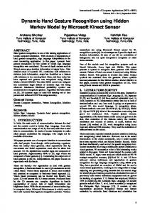
1. Introduction A biometric system is able to identify an individual based his physiological traits such as fingerprint, iris, hand and face or behavioural traits such as gait, voice and handwriting. Various biometric techniques have been described in the literature and many of them have been commercialised. Among them, the most popular ones are fingerprint identification and face recognition. However, all of these biometric techniques have own advantages and disadvantages according to user acceptance, cost and performance [1]. Biometric system using hand geometry measures is easy and cheap to set up and does not cause anxiety for user like fingerprint and iris systems. These are the major superiorities to other biometric systems. A limited amount of research has addressed the method of hand recognition using geometric measurements. Anil et al. [2] and Sanchez-Reillo et al. [3] proposed various geometric features of the hand such as width and length of fingers, hand size, and height profile. These two methods have some constraints for the user to place his/her hand on the platform. The user has to place his/her fingers between fixation pegs (figure 1). Cenker Oden et al. [4] presented an improved method to use implicit polynomials to model the finger, which removed the constraints of needing special hand
Figure 1: The constraints of placing hand (Four fixed pegs) The B-Spline curve has become popular in computer vision and pattern recognition in recent years. For example, cubic B-Spline curves have been used in edge detection schemes [5]. This technique achieves good noise immunity and preserves accurate localization. Cham [6] proposed an automatic B-Spline curve fitting technique for the representation of object boundaries in 2D images. Unser [7] even claimed that splines and wavelets provide a new perspective for pattern recognition. All these results encourage us to employ the B-Spline curves for hand recognition. In this paper, we present a novel hand recognition system that not only removes fixed-pegs for image acquisition but also represents fingers as B-Spline curves. The rest of the paper is organized as follows. In section 2, we present the details of preprocessing and B-Spline curve fitting. In section 3, we give the algorithm of
0-7695-2128-2/04 $20.00 (C) 2004 IEEE
computing the difference between two hand images from two individuals. In section 4 we report our experimental results (up to 100% of success in identification) and proposed future works.
2.1 Non-uniform B-Spline curve fitting A non-uniform B-Spline curve is defined as n
C (t ) = ∑ N i , p (t ) Pi
2. Preprocessing and B-Spline fitting Hand images are obtained with a CCD color digital camera, placed a fixed distance above the platform, where the user’s hand is placed. Because there are no fixed pegs, the user has greater freedom to place the hand as long as each finger is separate.
i =0
where {Pi } are the control points for the B-Spline curve and { N i , p } is the pth B-Spline basis functions defined as
N i , p = N i , p −1 (t ) ⋅
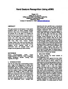
2.1 Preprocessing The original images are color. They are transformed into black and white binary images through thresholding (figure 2a), since there is a clear distinction in intensity between the hand and the background by design. A border following algorithm is applied to locate the boundary of the binary image [8]. After the extraction of boundary, the binary images are enhanced into a singlepixel-width boundary of the hand (figure 2b).
N i ,1
( x ′y ′′ − y ′x ′′) 2 (1) ( x′2 + y′2 )3/ 2 where x ′ , y ′ , x ′′ and y ′′ is the first and second order k=
coordinate changes along y and x, calculated from the neighbouring points (x, y). Five fingertips are the positive local extremes of curvature (figure 2b). On the other hand, four interfinger points are the negative ones (figure 2b). After obtains these landmarks, we can fit fingers with non-uniform B-Spline curves.
1 = 0
if
ti+ p − t t − ti + N i +1, p −1 ⋅ t i + p −1 − t i t i + p − t i +1
(3)
t i ≤ t ≤ t i +1
otherwise
where {t 0 , t1 ,..., t n + p } is a non-uniform knot vector. We choose a non-uniform B-Spline curve because it is more flexible and can reduce the fitting errors [6]. We assign the value of a knot vector according to the normalized arc-length distances between a pair of neighboured control points. There are two steps for the calculation of a knot vector. • We first generate an auxiliary vector {t i } , whose dimensionality is equal to the number of control points. It can be calculated as
0 Pi − Pi −1 t i = t i = t i −1 + n ∑ P j − P j −1 j =1 1
(a) (b) Figure 2: (1) A binary image (b) The boundary of the hand, five fingertips and four interfinger points. In order to find five fingertips and four interfinger points, we calculate the curvature of all boundary points. For each boundary point (x, y), its curvature K is estimated from:
( 2)
• means where computation. •
the
i =0 0