EPJ Web of Conferences 180, 02105 (2018) https://doi.org/10.1051/epjconf/201818002105 EFM 2017
Using the adsorption chillers for utilisation of waste heat from rotary kilns Karol Sztekler1*, Wojciech Kalawa1, Wojciech Nowak1, Sebastian Stefański1, Jarosław Krzywański2 and Karolina Grabowska2 1
AGH University of Science and Technology, A. Mickiewicza Av. 30, 30-059 Krakow, Poland Jan Dlugosz University, Armii Krajowej Av. 13/15, 42-200 Czestochowa, Poland
2
Abstract. Waste heat utilisation and its reclamation is important for increasing the efficiency of the electric power production and for decreased consumption of primary energy. Waste heat can be utilised for the electric power production or for manufacturing and processing purposes. According to long-term forecasts, the consumption of electric power with current consumption of about 150 TWh, can be increased to about 230 TWh in around 2040, what may lead to the increased energy consumption from fuels and the increased emission of harmful contaminants to the atmosphere. The cement subsector, next to the glass industry, is among the most power-consuming industries, and it consumes about 12-15% of total energy consumed by industry in total, whereas the CO2 emission from such industry exceeds about 5% in worldwide scale. In the cement sector, there is an increasing need for useful reclamation of waste energy, in order to obtain high energy-saving factors, and hence the financial and environmental benefits. In this paper the chances for waste energy reclamation from a rotary kiln are presented, with means of the used adsorption chillers.
1 Introduction The efficiency of energy utilised in the business is the important factor influencing on the level of manufacturing costs, company’s profits, competitiveness of products, on social upkeep and on standards of living of citizens. As a result, when the energy is used ineffectively, high consumption of energy resources and problems with natural environment contamination are observed. Strategic goal in the ecological and energy policy in Poland is currently the increased efficiency of energy economy. The energy efficiency is related with the increased competitiveness of Polish companies and with many other elements, when compared to other EU countries. The problem of energy efficiency is treated as priority, because the advancement in such field is very important for the execution of all energy policy goals and for the majority of ecological and climatic policy goals. A basic goal in the area of effectiveness, next to the goals stipulated in the directive, is currently energy consumption decreased with 20%, in comparison to forecasts for 2020, from the energy efficiency increase [1,2]. As it was mentioned, the cement sub-sector is among the most power-consuming industries, that consumes about 12–15% of total energy consumed by whole industry. A cement plant consumes in average about 4 GJ of energy in order to produce 1 tonne of cement (up to 5.4 GJ/t in China [3]), therefore it is among the most power-consuming manufacturing processes. The production of cement is related with the emission of many harmful substances, whereas carbon *
dioxide emission from the cement industry comprises about 5% of total worldwide emission originating from the activity of human being. Emission from the cement industry in Poland in 2002 amounted to about 7824 thousand tonnes, what can be interpreted as the unit emission of about 0.69 kg/tonne for the produced cement [1]. The yearly cement sales in Poland in 2014 amounted to 15.2 million tonnes, whereas in 2015 it was about 16.4 million tonnes and in 2016 it should be on the similar level [4]. According to long-term forecasts, the amount of cement sold may increase, what obviously generates the increased electric power consumption and the emission of gases, therefore all works in search for the decreased cement plant’s impact or the increased exploitation level for primary energy are advisable.
2 Methods for waste heat utilisation from the cement plant In the cement sector, there is an increasing need for useful reclamation of waste energy, in order to obtain high energy-saving factors, and hence the financial and environmental benefits. The waste heat was used for the first time in the cement industry more than 100 years ago. It was waste heat utilised from flue gases with means of the system of heating tubes. In the cement manufacturing process, much energy is irretrievably lost; decrease in such loses in a global scale with at least fraction of a percent generates visible savings from the combusted fuel.
Corresponding author:
[email protected]
© The Authors, published by EDP Sciences. This is an open access article distributed under the terms of the Creative Commons Attribution License 4.0 (http://creativecommons.org/licenses/by/4.0/).
EPJ Web of Conferences 180, 02105 (2018) https://doi.org/10.1051/epjconf/201818002105 EFM 2017
The increased thermal efficiency for rotary kilns is available with means of retrofit actions, such as: implementation and improvement in the heat exchanger construction, clinker coolers or other devices cooperating with the cement kiln. The most beneficial retrofit solution will be searched in this papers, that is related with the recovery of waste heat possible for implementation in the Rudniki Cement Plant nearby Czestochowa. Utilisation of the waste heat depends on its temperature in large extent, as well as on the speed of heat flow, its availability in a day and in a year. Possible and the most often used heat sources for reclamation purposes in Cement Plants are flue gases, radiation from the internal surface of the rotary kiln, a heat transferred by a hot clinker leaving the kiln, as well as a cooling air for a burned material (Fig. 1).
water in the range of 7–12°C, that can be used for airconditioning purposes. Adsorption chillers are characterised with low chilling performance coefficient (COP) ranging from 0.2 to 0.6, thus such systems are mainly dedicated in the fields where waste heat is at disposal [11,12,15]. Application of such type of installation enables the use of the waste heat from the rotary kiln.
3 Utilising waste heat from the Rudniki Cement Plant Rudniki Cement Plant nearby Czestochowa manufactures: cements (slag, mixed, namely multicomponent, lime, metallurgical), road adhesive (since 2009) and limestone dust. Rudniki and Chelm Cement Plants in the Cemex group are dominating in Poland in terms of waste utilisation as the alternative fuel. Rudniki Cement Plant has been in the ownership of the Cemex group since 2005. In the Rudniki Cement Plant two waste heat reclamation methods exist. The first one is using the heated air in the clinker cooling process as the secondary heat guided to the rotary kiln. The second waste heat utilisation method from the industrial installation is using flue gases received from the kiln, in order to dry raw materials fed to the limestone dust and to dry the coal in the ball mill [5,16]. 3.1. Radiating exchanger
Fig. 1. Heat balance of cement kiln [5].
Rudniki Cement Plant is equipped with three rotary kilns with capacity of 650 t/day and length of 140 m. Such rotary kilns are made from steel in the shape of elongated, cylindrical tube. They are inclined at the level of about 3–5%, what enables the movement of input material to the front of the kiln in a natural way. Maximum temperatures in the cement kiln are the flame temperature and temperature of gases in the sintering zone, where they reach 2000°C. Such high temperatures are reached in the kiln with means of the rotary kiln operating in counter current. Final product leaving the kiln reaches the temperatures of 900–1300°C. The kiln surface may reach a temperature exceeding 400°C and is another important heat loss source. Heat losses by convection and radiation may comprise about 8–15% of input energy [6,7,17,18]. Rotary kilns emit significant amounts of heat on the radiation route, that may be usefully exploited, for i.e. domestic hot water warming purposes for satisfaction of the Plant’s needs, or for the heated water used when powering the adsorption chillers. The external radiator exchangers may be found in the literature, that most often exist in the form of longitudinal series of tubes located coaxially on the cylindrical surface of the external layer of the rotary kiln or it has the semi-circular shape in profile, in the form of bent tubes (Fig. 2).
We can discern the following methods for waste heat utilisation in the cement plant: Utilisation of hot air from clinker coolers - it is used as the primary or secondary air for the combustion of coal dust or as a drying agent for the coal and input materials in the mills; The heat reclaimed from the rotary kiln’s surface - the hot kiln’s surface that can reach temperature exceeding 400°C enables the reception of heat with means of external heat exchangers located around the kiln; Heat utilisation from waste gases and clinker coolers air - the effective reclamation of waste heat from the stream of gases and air is possible with means of Clausius-Rankine watervapour circuits and Clausius-Rankine organic cycle (ORC), as well as with means of air turbine [6,7,8,9]. In this papers the utilisation of waste heat coming from the rotary kiln’s surface is contemplated, with means of the radiation exchanger that is used for the production of hot water t = 65°C used as the energy source powering the adsorption chiller. The adsorption chiller is the device, in which the water adsorption phenomenon in the silica-gel deposits or the zeolite deposits is used, that can be regenerated with the heat with temperature of about 55°C. Such a low powering temperature for the chiller opens a variety of possible applications for this device. The chiller may be powered by a geothermal heat, a thermal energy from solar collectors, a waste energy from some processes or a heat from district heating network. Description for operation of the adsorption chiller is presented in the literature [10–14]. Adsorption chillers can produce the chilled
2
EPJ Web of Conferences 180, 02105 (2018) https://doi.org/10.1051/epjconf/201818002105 EFM 2017
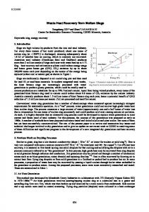
Fig. 3. Temperature distribution on the no. 4 kiln’s mantel.
It was assumed in the heat-flow evaluations, that the exchanger: will be made as a single-row screen made from seamless steel tubes; the screen will be made in the form of cylinder spur covering 1/6 of the rotary kiln circumference; minimum distance from the kiln 1m; the boiler seamless steel tubes are used for the construction, d 51 mm , water temperature with dimensions of: z = dw
44.6 mm
supplied to the radiator exchanger t1 = 10°C; distance between the tubes 0.15m; the heat exchanger length 8-12 m, maximum daily heat consumption for the plant 0.12 l/s; average temperature value on the kiln’s mantle at the section of 16-28 m t1 = 316°C ; energy supply is guided into the adsorption chiller in the form of water with temperature of t = 65°C, The assumed COP for the adsorption chiller COP = 0.42, when producing the chilled water with temperature of t = 12/7°C [12,13,14,15]. Thermal-flow evaluations are made according to the literature [19,20,21,22].
Fig. 2. The heat exchanger : a) in tube arrangement located coaxially on the external layer of the rotary kiln, b) in the arrangement of bent tubes [18].
The exchangers with oval or cylindrical tubes with ribs are also used in order to increase the heat exchange surface, and such exchangers are used in the places where media participating in the heat exchange are gases (air, flue gases) and any fluids (e.g. water, oils). An interesting solution for the heat recovery from the external surface of the rotary kiln is the axial superposition of fixed housing, that may cover up to about 80% of total kiln length. It forms the heat recovery chamber, with which an exhausting fan is connected, where the heated air from the surface of the kiln may be used in order to dry the coal.
4 Evaluation results Thermal-flow evaluations were made for the exchanger with length of 12 m and 8 m, according to the literature [19–22]. Where s is distance of the exchanger from the rotary kiln surface, m; t2 – the exchanger surface temperature, °C; Q1-2 – amount of the received heat from the kiln’s surface with means of the radiator exchanger, kWc; v – water volume stream heated to temperature of 65°C; Qch – cold production in the adsorption chillers, kWch (Table 1).
3.2. The selection of the exchanger’s operation parameters The proposed exchanger will have two functions in the cement plant, in the winter period it can be used for domestic hot water production purposes, and in the summer period the generated hot water will be used for powering the adsorption chiller and for production of the chilled water. Thermal-imaging measurement was used for the evaluation of temperature distribution on the kiln’s mantel, (Fig. 3), on the 16–28 m section of initial kiln’s length, where temperature was 348.7°C.
Table 1. Evaluation results for the exchanger with length of l = 12 m and l = 8 m. Exchanger length 12 m s m
3
t2 °C
Q1-2 kWc
v 3
Qch
dm /s kWch
Exchanger length 8 m s m
t2 °C
Q1-2
v
Qch
3
kWc
dm /s kWch
1.0 39.4 163.34 0.716 68.60 1.0 40.2 64.80
0.285 27.22
1.1 39.4 139.68 0.613 58.67 1.1 39.8 55.45
0.243 23.29
1.2 39.3 121.33 0.532 50.96 1.2 39.8 48.16
0.211 20.23
1.3 39.3 106.75 0.468 44.83 1.3 39.8 42.37
0.186 17.79
1.4 39.2
0.165 15.83
94.95 0.416 39.88 1.4 39.8 37.68
EPJ Web of Conferences 180, 02105 (2018) https://doi.org/10.1051/epjconf/201818002105 EFM 2017 Exchanger length 12 m s m
t2 °C
Q1-2 kWc
v
Qch
3
dm /s kWch
4.
Exchanger length 8 m s m
t2 °C
Q1-2
v
Qch
3
kWc
dm /s kWch
1.5 39.2
85.24 0.374 35.80 1.5 39.8 33.83
0.148 14.21
1.6 39.1
77.14 0.338 32.40 1.6 39.8 30.61
0.134 12.86
1.7 39.1
70.30 0.308 29.53 1.7 39.9 27.89
0.122 11.71
1.8 39.1
64.46 0.283 27.07 1.8 39.9 25.58
0.112 10.74
1.9 39.1
59.43 0.261 24.96 1.9 40.0 23.58
0.104
9.90
2.0 39.1
55.06 0.241 23.12 2.0 40.1 21.84
0.096
9.17
3.0 39.1
30.78 0.135 12.93 3.0 42.9 12.17
0.054
5.11
3.1 39.1
29.42 0.129 12.36 3.1 42.5 11.61
0.051
4.87
3.2 39.1
28.17 0.124 11.83 3.2 41.7 11.10
0.049
4.66
4.0 39.3
20.86 0.092 8.76
0.0367 3.47
4.0 41.7
8.26
5.
6. 7. 8. 9. 10.
4 Conclusion
11.
The assumed 0.12 l/s domestic hot water demand in the Plant can be satisfied with both proposed exchanger versions. The exchanger with length of 12 m may reach the values of volume yield in the range of 0.716–0.092 l/s, whereas in the exchanger with length of 8 m: 0.285– 0.036 l/s. In case of the first exchanger, it should be placed at least at distance of 3m, in order to obtain the yield of about 0.122 l/s. In case of the second exchanger, when it is placed at distance of 1.7 m, the 0.122 l/s yield can be obtained. Maximum thermal output possible in case of the installed 12m and 8m exchanger at distance of 1m, with simultaneously obtained about 163 kWc and 64.80 kWc, respectively, similarly to the case of the installed adsorption pump, it enables the production of about 68 kWch and 27.2 kWch. Whereas, when simultaneous production of domestic hot water for the plant’s needs and cold is assumed, we can produce with means of the 12-meter-long exchanger about 56 kWch; and in case of the 8-meter-long exchanger about 15 kWch. Such solutions provide complete satisfaction of domestic hot water and cold needs in the Plant, with relatively small investment costs, what also enables primary energy savings, that would be otherwise used in domestic hot water and cold production.
12. 13. 14. 15. 16. 17. 18. 19. 20. 21. 22.
Acknowledgment The paper was funded from government money Faculty of Energy and Fuels number 11.11.210.216.
References 1.
2. 3.
B. Vanderborght, B. Brodmann, The Cement CO2 Protocol: CO2 Emissions Monitoring and Reporting Protocol for the Cement Industry (Guide to the Protocol 1.6, 2001) K. Pikoń, M. Kajda-Szcześniak, M. Bogacka, Chemical Industry 94 1548 (2015) (in Polish) E. Mokrzycki, A. Uliasz-Bocheńczyk, Energy Policy 9 (2006)
4
http://www.polskicement.pl/aktualnosci/W_2015_ro ku_wzrost_sprzedazy_cementu_w_Polsce_do_16_ mln_ton-308 (2017) K. Sztekler, M. Komorowski, M. Tarnowska, Ł. Posak Proc. of the Int. Conf. on the Sustainable Energy and Environment Development, E3S Web of Conferences 10 (2016) A. Atmaca, R. Yumrutas, Appl. Thermal Eng. 66 435 (2014) J. Duda, The Scientific Works of the Institute of Ceramics And Building Materials 32 (2012) (in Polish) S. Karellas, A. Leontaritis, G. Panousis, E. Kakaras, Energy 58 147 (2013) F. Campana, M. Bianchi, L. Branchini, A. De Pascale, A. Peretto, M. Baresi, Energy Conv. and Management 76 244 (2013) R. Wang, L. Wang, Wu J, Adsorption Refrigeration Technology: Theory and Application (2014) K. C. Ng, B. B. Saha, Advances in Adsorption Technology (2010) X. Wang, H.T. Chua, Int. J. of Refrig. 30 1417 (2007) Q. W. Pan, R. Z. Wang, L. W. Wang, D. Liu, Int. J. of Refrig. 67 336 (2016) M. Gwardera, K. Kupiec, Chemical Engineerign and Equipment 50 38 (2011) (in Polish) M. Chorowski, Nowa Energia 4 (2014) K. Sztekler, K. Wojciechowski, M. Komorowski, M. Tarnowska, Proc. of Energy and Fuels Conf., E3S Web of Conferences 14 (2016) S. Żurakowki, S. Hojarczyk, Rotary kilns – desing and contruction (WNT, Warsaw 1969) (in Polish) A. Caputo, P. Pelagagge, P.Salini, Appl. Thermal Eng. 31 2578 (2011) J. P. Holman, Heat Transfer 10th Edition (McGrawHill, New York, 2010) T. Hobler, Heat transfer and heat exchangers (PWT, Warsaw, 1959) (in Polish) U. Lubczyńska, Applied hydraulics (Kielce 1996) (in Polish) A. Sala, Radiaton heat transfer (WNT, Warsaw, 1982) (in Polish)