and a forwarder, which collects the logs in a tray, and carries them to the ... ment allows a forestry company to monitor the operation of a large ... an IP network.
Virtual Environment Teleoperation of a Hydraulic Forestry Crane Simon Westerberg∗, Ian R. Manchester∗, Uwe Mettin∗ , Pedro La Hera∗ , Anton Shiriaev∗,†
Abstract— A teleoperation system has been developed for a hydraulic crane, of the type used on a forwarder vehicle, which travels off-road and collects logs cut by a harvester. The system developed consists of a 3D virtual environment, which allows the user to input a desired position for the crane tip using either the mouse or a joystick. The desired position is then transmitted (via UDP/IP) to a local control system. The crane is a redundant manipulator, so movements of the individual links are calculated using a pseudoinverse method, and controlled using PIDs with friction compensation. Encoder data from the crane links are continuously sent back to the user side, and the crane’s movement is visualized in the virtual environment. The system has been tested on a real forwarder crane, experimental results and a video of the system’s performance are provided.
I. I NTRODUCTION The Swedish forestry industry has a long-term goal of developing autonomous and semi-autonomous forestry vehicles [1], [2]. There are two main types of off-road vehicle used in the forestry industry: a harvester, which fells and delimbs the trees, and cuts the trunk into logs of a predetermined size, and a forwarder, which collects the logs in a tray, and carries them to the nearest road for collection. A forwarder is shown in Figure 1. Control of the forwarder can be divided into two distinct tasks: navigation of the vehicle itself, and operation of the on-board crane. It is the latter task which we consider in this paper. This paper describes implementation and experimental testing of a virtual-environment-based remote control and visualization system for such a crane. The system presented here is to be considered a partial solution. At present, the virtual environment is constructed based on information from the sensors on board the crane, and does not include any dynamic sensing of objects within the environment. The latter is currently under development. A. Virtual environment–assisted teleoperation Virtual environments systems have been successfully used for teleoperational tasks. Gravez et al. [3] use a virtual model of a hydraulic arm and its surroundings to perform different tasks in a radioactive environment. Their system allows visual feedback as well as high-level motion control. There are several other reports of successful implementation of virtual-environment-based teleoperation systems for other This work has been supported by the Centre for Intelligent Off-Road Vehicles at Ume˚a University, Komatsu Forest AB, and the Kempe Foundation. * Department of Applied Physics and Electronics, Ume˚a University, SE901 87, Sweden. † Department of Engineering Cybernetics, Norwegian University of Science and Technology, N-7491 Trondheim, Norway.
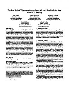
Fig. 1.
A forwarder: the Komatsu 860.1.
classes of systems in the literature, see, e.g. [4], [5], [6] and references therein. The use of virtual environments in teleoperation has several advantages compared to teleoperation with streaming video as visual feedback [7]. One obvious advantage is the possibility to change the view of the virtual environment. When video is used for feedback, the physical cameras need to be attached to the machine and placed where they do not risk to be damaged by collisions. The virtual environment, however, can be fused from many different sensors at different locations, and the virtual cameras can be placed in any location and moved around freely. This gives the user a good overview and also the possibility to adapt the view to the task that is currently performed. E.g., if an obstacle is present, the operator can view the scene from another direction so that the line-of-sight is not blocked by the obstacle. Additionally, the communication of streaming video requires large bandwidth in order to have reasonable image quality. This is an important issue in the forest, where Internet connections have a very limited capacity. With virtual environments, the information flow between the machine and the operator can be restricted to the most relevant features of the environment, such as the position and size of a log, whereas less important details in e.g. textures can be discarded. Another advantage with virtual environments is the possibility to easily add visual operator assisting features. For
Fig. 2.
The system architecture
instance, irrelevant details about the environment can be hidden, while more important information can be emphasized, in order to let the operator focus on important information. Furthermore, information that is not visual in the physical world, like optimal crane-arm trajectories, can be added. By changing the modality of the information, non-visual object properties can be made visible in the virtual environment. E.g., color can be used to represent the temperature of an object. This makes virtual environment useful not only for teleoperation. Even in normal operation, a virtual environent can give the operator information that is hard or impossible to see with his own eyes. A further goal is to make the control of the crane more intuitive. In current forest machines, the driver must directly control six hydraulic valves using two 3-degree-of-freedom joysticks. Each joystick motion corresponds to one crane function, e.g. increasing the angle between two links, or extending the telescopic arm, etc. Learning to control the crane tip efficiently takes years of training [1]. A more intuitive way to control the crane is to directly specify the position of the crane tip, and generate the required hydraulics inputs by computer control. When certain tasks are automated and thus performed without human intervention, a virtual environment is useful for monitoring the machine’s actions. Furthermore, even if a crane is completely controlled by a driver, a virtual environment allows a forestry company to monitor the operation of a large fleet of vehicles in an intuitive manner. II. S YSTEM A RCHITECTURE Figure 2 shows the architecture of the teleoperation system. The system consists of two subsystems, connected through an IP network, either a LAN or the Internet. One subsystem is at the location of the crane, with physical connections to sensors and actuators. Besides the sensorequipped crane and the real-time device, this subsystem contains an ordinary PC. The PC is responsible for the communication between the real-time system and the network. The second subsystem is at the location of the operator. It provides the operator with visual feedback, as well as with an interface for controlling the crane. For visualization
Fig. 3.
The crane laboratory at Ume˚a University.
and user interface, the CraneVE software was developed. The software is written in C++ and uses a scene graph as the virtual environment data structure, using the OpenSceneGraph library. This subsystem consists of a PC that runs the CraneVE software as well as the software that reads input from the user. The operator uses a joystick and/or a mouse to enter the input to the system. The output consists of visualization on a monitor. The crane PC and the operator PC are connected through an IP network. Data transmissions are sent using UDP, which has a low overhead and reduces the bandwidth use. In one direction, the transmitted data consists of sensor data, i.e. link angles and telescope extension. In the other direction, it consists of 3D positions that are used to control the crane. Since only a few bytes are used to represent the transmitted information, the bandwidth requirement is low, even if the sensor data are updated frequently. III. C RANE C ONTROL H ARDWARE The following experimental equipment has been installed at a laboratory at Ume˚a University: • CRANAB 370RCR hydraulic forwarder crane, • three joint-position encoders, 4000 pulses per turn, the telescope extension is measured by an encoder connected to a retracting wire, • dSPACE MicroAutoBox real-time protyping hardware, with on-board PowerPC CPU, • RapidPro power amplification unit and signal conditioners. The 370RCR crane is somewhat smaller than most cranes used on real forwarders, but was chosen due to space restrictions in the laboratory. It’s operational principle and dynamics are, however, very similar. The experimental setup is shown in Figure 3. IV. U SER I NTERFACE The user interface is shown in Figure 4. The operator is presented with a view of the virtual model of the crane, as well as of the surrounding environment.
Fig. 4.
The user interface for the crane teleoperation system.
On the left side is the view of the virtual environment. The viewpoint can be moved around freely by the user using the mouse: the operator can move and rotate the camera, as well as zoom in and out. This allows the user to zoom out for an overview, or focus on details of the environment that are important for a certain task. The other two view panes have positions and directions that are fixed relative to the crane. That is, for any configuration (rotation and translation) of the crane, the cameras are always directed towards the crane. The top right view pane shows the crane from the side, while the bottom right view pane shows the crane from above. This allows the operator to always have a detailed view over the crane and the environment near the crane. Virtual environments are suited for the introduction of operator assisting features. As one example of this, visualization of the crane workspace has been implemented. This can be seen in Figure 5. A. Target Specification The user can specify the target position of the crane-tip in a number of different ways. One way is to use the mouse to click on the top right camera view. This will result in a position in the vertical plane. The second method is to use an ordinary joystick to move a pointer in the virtual environment. A 2-axis joystick is used and two buttons are used to simulate a third axis for full 3D motion. When the user presses a button, the current position of the pointer is sent to the control system. The crane motion that is required to move the crane tip from the current crane position to the target point is then calculated. The motion can be calculated to be optimal with regard to e.g. speed or energy efficiency. In the following section we describe a simple motion-planning algorithm which can be calculated on-line. If several subsequent target points are specified, the target points become waypoints on a target trajectory. The crane tip will then visit each waypoint in order. The next step is to transfer more responsibility from the
Fig. 5. High-level control with collision avoidance. The yellow path shows the trajectory generated by the collision avoidance algorithm in order to avoid the obstacle (the green box) while moving towards the tray.
operator to the control system. This means that certain tasks or processes are automated and performed autonomously by the system. As an example of an activity where the computer has increased responsibility, a simple collision-avoidance algorithm has been implemented in the CraneVE software. When collision avoidance is enabled, the system performs collision detection between the user-specified trajectory and the objects in the scene. If the user specified trajectory is blocked by an object, a new trajectory is calculated such that the crane tip passes above the object and avoids the collision. The collision avoidance algorithm is explained in Figure 6. V. C RANE -S IDE C ONTROL The configuration of the crane is represented by a threedimensional vector, q = [θ2 , θ3 , d]0 . From basic trigonometry one can derive the forward kinematics equations, giving the Cartesian coordinates from a known link configuration: c := [x, y]0 = f (q).
(1)
However, the low-level control objective is to reach a particular point in two-dimensional space, i.e. a particular Cartesian coordinate c? = [x? , y? ]0 . Since there are three degrees of freedom in the crane, this is an underdetermined problem, and hence has infinitely many solutions. We now describe the method we use to choose a corresponding q? such that f (q? ) = c? , it is conceptually similar to the methods presented in [8], [9], [10]. Differentiating the above equation, we get: c˙ = F (q)q, ˙
(2)
where F (q) is the Jacobian of f (q). We wish to calculate a movement in q that would correct the current positioning error c? − c. Again, generating q˙ from c˙ is an underdetermined problem, and has infinitely many solutions. We choose to find
the solution which minimizes a configuration-dependent cost function of the form: J = q˙0 P (q, c) ˙ −1 q, ˙
(3)
where P (q, c) ˙ is a positive definite matrix for all q and c. ˙ This choice of cost function is quite simplistic, but it has the advantage that the resulting solution can be calculated analytically: q˙ = P (q, c)F ˙ (q)0 [F (q)P (q, c)F ˙ (q)0 ]−1 c. ˙
(4)
The matrix F (q)P (q, c)F ˙ (q)0 is three-by-three, and its inverse can be expressed analytically in terms of its elements. The formulas are too lengthy to present here, but they are not difficult for real-time computation, in comparison to an iterative scheme that another choice of cost function would require. In our system, P (q, c) ˙ is chosen to be of the following form: w1 p1 (q, c) ˙ 0 0 . (5) 0 w2 p2 (q, c) ˙ 0 P (q, c) ˙ = 0 0 w3 p3 (q, c) ˙
Fig. 6. The collision avoidance algorithm. (a) Assume that p is the end point of the current path. Let q be a new target point defined by the operator. (b) If q collides with an object, find a safe point q 0 above the bounding sphere of the object. (c) If the path p → q 0 collides with an object, find a safe point c0 above the center of the object. Let m and n be the middle point of each sub-path p → c0 and c0 → q 0 respectively. (d) Find safe points m0 and n0 above m and n such that they are outside of the bounding sphere of the colliding object. The final path will be p → m0 → c0 → n0 → q 0 .
The values w1 , w2 , w3 represent the desired contribution from each link to the overall movement. If one of them is zero, the corresponding link is stationary and the other two links are used to generate the motion. The functions p1 (q, c), ˙ p2 (q, c), ˙ p3 (q, c) ˙ are there for “protection”: if one of the links is approaching the limit of its working range, its contribution should be smoothly reduced towards zero, and the other links should take over. We now describe how they are calculated. For each i = 1, 2, 3, let qimax and qimin be the maximum and minimum allowed values of qi , let δi be a constant smaller than (qimax − qimin )/2, and let φi (q) be a smooth function such that: • • •
φi (qimin ) = 0, φi (qimax ) = 0, φi (s) = 1 for all s ∈ [qimin + δi , qimax − δi ]
Then pi (q, c) ˙ is calculated like so: Algorithm 1: 1) Set p1 (q, c) ˙ = p2 (q, c) ˙ = p3 (q, c) ˙ = 1, 2) calculate q˙?0 from Equations (4) and (5), 3) for each i = 1, 2, 3, if max 0 • qi − qi < δi and q˙?,i > 0,or min 0 • qi − qi < δi and q˙?,i < 0 then pi (q, c) ˙ = φi (qi ). � We have then the following closed-loop control algorithm, which generates control signals u1 , u2 , u3 from a desired Cartesian set-point c? and the measurements q1 , q2 , q3 : Fig. 7.
Basic geometry of the crane.
−0.9
0.8
−1
0.7
−1.1
Second link angle (rad)
First link angle (rad)
0.9
0.6
0.5
−1.2
−1.3
0.4
−1.4
0.3
−1.5
0.2 −1
0
Fig. 8.
1
2
3 4 Time (s)
5
6
7
−1.6 −1
8
Step response for the first link, θ2 .
−0.5
Fig. 9.
0
0.5
1 Time (s)
1.5
2
2.5
3
Step response for the second link, θ3 .
1.4
Algorithm 2: q? (0) = q˙? =
q kP (q, c)F ˙ (q)0 [F (q)P (q, c)F ˙ (q)0 ]−1 (c? − f (q? )),
u1 u2
= =
C1 (s)[q1 − q?,1 ], C2 (s)[q2 − q?,2 ],
u3
=
C3 (s)[q3 − q?,3 ].
Telescope position (m)
1.2
1
0.8
0.6
0.4
(6)
0.2
0 −1
where k is a large positive gain, and C1 (s), C2 (s), C3 (s) are PID controllers tuned for each link of the crane, and P (q, c) ˙ is calculated at each sample time from Algorithm 1. � Each control signal is further modified to compensate for the large Coulomb friction present in the hydraulics actuators, see [11] for details, see also [12] for similar work. The vector q? quickly converges to a feasible target, satisfying f (q? ) = c? . Following this, the individual link positions q1 , q2 , q3 are driven more slowly to the corresponding values from q? . VI. E XPERIMENTAL R ESULTS A. Individual Link Positioning In Figures 8, 9, and 10 we see the step responses of the individual links, as controlled by the PID controllers C1 (s), C2 (s), C3 (s) along with the friction compensators. It is clear that the first link is by far the slowest, which is reasonable since it must drive by far the greatest mass. The second link and the telescope converge at similar rates, but the telescope is much smoother and easier to control, since it has the least mass to drive. We chose the control contributions in Algorithm 2 such that the links with the best control are used most. The following values were found to be reasonable in experiments: w1 = 0.5, w2 = 1, w3 = 1.5. Overall, we were able to make all links converge to the desired positions with zero steady-state errors, sufficient speeds, and without oscillations.
−0.5
Fig. 10.
0
0.5
1 Time (s)
1.5
2
2.5
3
Step response for the telescope, d.
B. Teleoperation Experiment Accompanying this paper is a video of the teleoperation system in action (a higher resolution version is also available online [13]). The user clicks the mouse at a sequence of points in the virtual environment, and the crane can be observed moving to those points. Figure 11 shows the x and y setpoints and crane trajectories from the same experiment as featured in the video. It can be seen that in general the system converges quickly (in two to four seconds) to the desired setpoint. There is an interesting effect visible at around 17 seconds, and again at 30 seconds. When the desired motion is large in one direction, but small or zero in the other, we still can observe a noticable deviation in the latter dimension. This is because, with a large k in Algorithm 2, q? converges very quickly to its final value satisfying f (q? ) = c? , and then each link is driven to its desired value at a slower rate. In particular, the first link is much slower than the other two. This means that the end-effector will not in general follow a straight line path between two points in Cartesian space. VII. C ONCLUSIONS
AND
F UTURE W ORK
The virtual environment-based teleoperation system reported in this article can be considered proof of concept. The system is also useful as a tool for further research and development in the area of remote crane control.
Vertical position (m)
3.5
3
2.5
2 15
20
25
30
35
40
45
50
Horizontal position (m)
4.5 Target True position
4 3.5 3 2.5 2 15
20
25
30
35
40
45
50
Time (s)
Fig. 11. Horizontal and vertical positioning during the teleoperation experiment.
However, the system is far from ready to be used in real forest machines. A virtual environment-assisted teleoperation system depends on the virtual representation being accurate, and the main problem right now is the lack of knowledge about obstacles in the environment. In order to correct this, we need a reliable method to detect and classify different objects near the crane. The classification problem is quite difficult: the system must be able to distinguish between rocks, trees, logs, branches and mud. It also needs to reliably detect any human inside the safety area. A number of different technologies are under investigation to address this problem. Different sensor systems like stereo cameras, laser scanners and structured light systems [14] can be used to extract information from the environment. Another direction of our current work is to implement and test a similar system on a real forwarder crane, provided by Komatsu AB. Due to reasons of confidentiality, we are not able to publish the results of these experiments, but a video showing an early test is available online [15]. R EFERENCES [1] U. Hallonborg, “F¨orarl¨osa skogsmaskiner kan bli l¨onsamma (Unmanned forestry machines can be competitive)” (in Swedish), Skogforsk Results, No 9, 2003. [2] M. Brander, D. Eriksson, B. L¨ofgren, “Automation of knuckleboom work can increase productivity”, Skogforsk Results, No 4, 2004. [3] P. Gravez, C. Leroux, M. Irving, L. Galbiati, A. Raneda, M. Siuko, D. Maisonnier, and J. D. Palmer, “Model-based remote handling with the MAESTRO hydraulic manipulator”, Fusion Engineering and Design, vol. 69, no. 1, pp. 147–152, 2003. [4] L. Fl¨uckiger, L. Piguet, and C. Baur, “Generic robotic kinematic generator for virtual environment interfaces”, in SPIE Telemanipulator and Telepresence Technologies, Vol. 2901, pp. 186–195, 1996. [5] R. Safaric, R. M. Parkin, C. A. Czarnecki, and D. W. Calkin, “Virtual environment for telerobotics”, Integrated Computer-Aided Engineering, vol. 8, no. 2, pp. 95–104, 2001. [6] L. A. Nguyen, M. Bualat, L. J. Edwards, L. Flckiger, C. Neveu, K. Schwehr, M. D. Wagner, and E Zbinden, “Virtual reality interfaces for visualization and control of remote vehicles”, Autonomous Robots, vol. 11, no. 1, pp. 59–68, 2001.
[7] A. Kheddar, R. Chellali, and P. Coiffet, “Virtual environment-assisted teleoperation” in Handbook of Virtual Environments: Design, Implementation and Applications, 2001, ch. 48, pp. 959-998. [8] A. A. Mohamed and C Chevallereau, “Resolution of Robot Redundancy in the Cartesian Space by Criteria Optimization”, in Proceedings of the IEEE International Conference on Robotics and Automation, Atlanta, GA, 1993, pp. 646-651. [9] L. Beiner, “Minimum-Force Redundancy Control of Hydraulic Cranes”, Mechatronics, vol. 7, no. 6, pp. 537–547, 1997. [10] L. Beiner and J. Mattila, “An improved pseudoinverse solution for reduntant hydraulic manipulators”, Robotica, vol. 17, pp. 173–179, 1999. [11] P. La Hera, U. Mettin, I. R. Manchester, A. Shiriaev, “Identification and Control of a Hydraulic Forestry Crane”, submitted to the 2008 IFAC World Congress, available on request. [12] M. E. M¨unzer, “Resolved Motion Control of Mobile Hydraulic Cranes”, PhD Thesis, Aalborg University, Denmark, 2002. [13] Video of crane virtual environment, available online at www.tf e.umu.se/f orskning/Control Systems/M ovies/ virtual environment exp.AV I [14] S Lee, J Choi, D Kim, J Na, S Oh, “Signal Separation Coding for Robust Depth Imaging Based on Structured Light”, in Proceedings of the IEEE International Conference on Robotics and Automation, Barcelona, 2005. [15] Video of experiment on forwarder, available online at www.tf e.umu.se/f orskning/Control Systems/M ovies/ f orwarder crane exp.AV I