Rev. Fac. Ing. Univ. Antioquia N.° 64 pp. 45-56. Septiembre, 2012
Voltage space vector‘s computation for current control in three phase converters Computo del vector espacial de voltaje para control de corriente en convertidores trifásicos Alberto Berzoy* 1 Julio Viola, José Restrepo Universidad Simón Bolívar. Edi®cio ELE, PB, O®cina 019. Valle de Sartenejas, Caracas, Venezuela.
1
(Recibido el 24 de marzo de 2011. Aceptado el 3 de septiembre de 2012) Abstract This work presents two current loop techniques, for three phase voltage source converters (VSC) used as controlled recti®ers (CR) operating at unity power factor. The ®rst one is based on choosing the best natural vector, among the natural space vectors produced by two level voltage source inverters, with the use of a cost function. The second one is based on computing and synthesizing a space vector such that an absolute minimum in the cost function is obtained. The ®rst algorithm is a simple method that presents power factor correction and good total harmonic distortion compensation. The second algorithm provides a novel and closed form formula to calculate the optimum voltage vector applied by the converter. In this method, pulse width modulation (PWM) is required to modulate the voltage vector that controls directly the line current, to follow the current reference. The simulations and experimental results show the advantages of the proposed control algorithm. ---------- Keywords: Current control, active ®lter, power factor, predictive control Resumen Este trabajo presenta dos técnicas de control de corriente para convertidores trifásicos de voltaje trabajando como recti®cadores controlados, operando con factor de potencia unitario. El primer algoritmo está basado en la escogencia del mejor vector natural, entre los 7 vectores espaciales naturales del convertidor de dos niveles de voltaje trifásico, mediante una función de costo. El segundo está basado en el cómputo y síntesis del vector espacial óptimo de convertidores trifásicos tal que el se obtiene el vector que proporciona un mínimo absoluto de la función de costo. El primer algoritmo es un * Autor de correspondencia: teléfono: + 058 + 212+906 4012, correo electrónico:
[email protected] (A. Berzoy)
45
Rev. Fac. Ing. Univ. Antioquia N.° 64. Septiembre 2012
método sencillo que controla muy bien el factor de potencia y presenta una considerable compensación del contenido armónico. El segundo algoritmo provee una nueva formula cerrada para calcular el vector de voltaje óptimo aplicado al convertidor. Para este segundo método se necesita generar la señal de control con un modulador de ancho de pulso para así controlar directamente la corriente de línea permitiendo seguir la referencia de corriente. Las simulaciones y resultados experimentales muestran las ventajas del algoritmo propuesto. ---------- Palabras claves: Control de corriente, ®ltro activo, factor de potencia, control predictivo
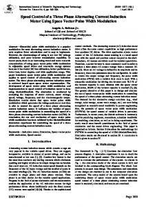
Introduction Nowadays almost every electric and electronic device is powered by a bridge diode recti®er which is a source of harmonics in the line current. These harmonic components deform the line current, create voltage unbalances, voltage losses in the point of common coupling and cause power inef®ciency. International Standard IEC 610003-2 establishes limits for harmonic currents content in equipment drawing less than 16A per phase from the mains. The International Standard IEC 61000-3-12 deals with levels of harmonic currents injected by equipment drawing between 16A and 75A per phase. Both standards can be met by adding passive power ®lters using simple and robust circuitry. Those ®lters, however, are not capable of operating in all the input range and do not guarantee sinusoidal input currents. In order to solve these problems, single and three phase voltage source converters have been proposed and investigated as controlled recti®ers [1-8] and active power ®lters (APF) [9-15]. Active power ®lters play and important function in reducing harmonic current contamination in lines providing a wide range of operation and almost perfect sinusoidal input current in both, single and three phase equipment. The topology used in this paper is a voltage source converter (VSC) shown in ®gure 1, that can be used as controlled recti®er or active power ®lter, while using the same proposed algorithm. An additional feature obtained with this converter topology is the possibility of power regeneration from the DC bus to the supply grid.
46
Different techniques have been proposed to perform the control of these converters which can be classi®ed in: direct current control [8, 1012, 14, 15], voltage oriented control [6], virtual ¯ux orientation control [16], direct power control (DPC) [2, 3]. The control technique proposed in [3] have some interesting advantages, such as high dynamic response, basic open loop operation, low sensibility to parameter variations and simplicity in implementation. Using the advantages of the DPC algorithm shown in [3], this paper presents a simple technique based on predictive current control, combining the advantages of direct current control and predictive DPC. Additionally to its simplicity, the control algorithm does not require the computation of the active and reactive power as in DPC, and achieves a similar result.
Three phase converter The three-phase two-level voltage source converter used as controlled recti®er with voltage output is shown in ®gure 1a, which is composed of three well de®ned structures: three inductors with its parasitic resistance acting as coupling between the AC sources and the converter active front end, a three-phase bridge composed of six IGBTs and a DC bus with its corresponding capacitor. To develop the mathematical model of the recti®er shown in ®gure 1a, it is useful to suppose that each phase of the recti®er can be represented as the circuit depicted in ®gure 1b.
Voltage space vector‘s computation for current control in three phase converters
(a)
(b)
Figure 1 a) Three phase bridge recti®er b) Single phase Model or branch model recti®er From the circuit in ®gure 1a and using space vector notation the following equation is obtained: (1)
(5) The line current space vector can be expresed as:
where is the line voltage space vector, is the line current space vector and is the converter’s voltage space vector.
(6) where
Decomposing (1), the model of the controlled recti®er in “xy” coordinates is:
is the present sampled value of line current vector and is the estimated value for line current at the next control cycle. is the control period. From (5):
(2)
(7)
(3)
by replacing (7) in (6) and neglecting the resistive component of the input inductance, the next current value will be:
where: (8) (4)
Control strategies
Equation (8) is an estimate of the next line current value which depends of the VSC’s voltage space vector . Depending on the switching states, has 7 possible space vectors shown in table 1.
Converter’s vector selection Equation (1) represents the converter’s model. A discrete time version of this equation is obtained by the following ®rst order approach:
47
Rev. Fac. Ing. Univ. Antioquia N.° 64. Septiembre 2012
Table 1 Converter voltage space vector
Vectores
Switches A
B
C
A
B
C
X
Y
0
0
0
0
0
0
0
0
0
0
1
0
1
0
0
1
1
0
1
0
0
0
1
0
1
1
1
0
1
1
1
0
0
The current error is de®ned as the difference between the reference current and the measured line current:
0
0
0
Replacing the reference in (9), the current error can be written as:
(11)
(9) In order to get unity power factor operation the current taken by the controlled recti®er from the mains must be a scaled version of the sinusoidal line voltage. The current reference will be then: (10) where G is a scale factor used to build the current reference from the measured line voltage. For G>0 the recti®er will operate in direct mode carrying power from the grid to the load at unity power factor, while for G