separate the application from any concrete UI. The semantic representa- ... While it has been recognized, that the desktop metaphor is not suited for wearable computing [8] ... A light background color is recommended for hand-held interfaces, ...
Wearable Computing for Aircraft Maintenance: Simplifying the User Interface Tom Nicolai, Thomas Sindt, Hendrik Witt, J¨orn Reimerdes, and Holger Kenn Universit¨ at Bremen, Germany Center for Computing Technologies (TZI) {nicolai, tsindt, hwitt, jrei, kenn}@tzi.de
Abstract. In this paper we present results from the realization of a wearable computing system with the goal to shorten the maintenance process in the aircraft industry. The project combines knowledge management with wearable computing to enable instant access to an electronic logbook, aircraft manuals, and experience knowledge. This research is part of an ongoing project which is carried out in cooperation with an aircraft company. The paper elaborates on user interface issues for a hybrid wearable/hand-held interface with an abstract representation to separate the application from any concrete UI. The semantic representation of maintenance data as well as clothing aspects are also addressed.
1
Introduction
The use of wearable computers in professional environments is an applied research topic that has gained attention in the recent years. The application of wearable computing can lead to increased labor efficiency and thus can be a tool to reduce cost. However, end user acceptance is critical for the success of a wearable computing solution [1]. As an application domain for professional wearable computing, we chose the operation and maintenance of large passenger aircrafts. The airline industry is characterized by significant cost pressure that has increased over the recent years with the increase of fuel prices. A key figure in the economically efficient operation of an aircraft is the ratio of actual in-flight time vs. ground time used for refueling, restocking, passenger boarding and maintenance. Under these circumstances, optimized ground procedures can directly convert to a cost advantage over competitors. Another key figure is the amount of passengers per flight which led to the construction of new classes of passenger airplanes with a seating capacity of over 500 passengers. Cabin operation on these planes either needs more personnel or optimized procedures to maintain safety standards and passenger satisfaction. For this, we propose the application of wearable computing. Results from user surveys and the corresponding wearable system design has already been presented in [2]. The main goal of this system design was an increase in efficiency, i.e. maintenance procedures should use less time, thus reducing ground time. In this paper, we focus on specific aspects of the implementation that are intended to increase
user acceptance. The basis for our research are the user interviews conducted with aircraft maintenance personnel from August to October 2003. From this, we compiled a number of subtasks that are part of the maintenance process and that have to be supported by wearable computing. Identification of required maintenance To begin his work, the maintenance technician has to receive a list of maintenance tasks that are to be executed. This list is created by compiling maintenance requests from the electronic logbook system of the aircraft, from maintenance-related entries in the avionics system of the aircraft and from standard maintenance procedures published by the aircraft manufacturer. Finding task-related documents While executing one of the maintenance tasks, the technician may have to search for a solution to the problem he is currently working on. Therefore, he may have to consult maintenance reports written by other technicians and other documentation ressources. Documenting the work After completing a maintenance task, the technician has to file a maintenance report documenting his work. To achieve user acceptance, the wearable computing system must not only support the tasks it is used for but also not impede tasks when it is not actively used, i.e. the actual repair work that often consist of delicate manual tasks. We have thus identified two critical aspects of system design: The user interface of the wearable computer that is critical for user acceptance while the wearable computing system supports the user in his current task and the integration of the wearable computing system in the clothing of the user that is critical when the user is not actively using the system. The paper is organized as follows: After a review of related work in wearable maintenance, wearable user interfaces, and knowledge management, aspects of the developed user interface are discussed in section 3. The next section gives a description of clothing issues and section 5 describes the knowledge management system to process maintenance data. The paper concludes with section 6.
2
Related Work
The support of working processes with mobile and wearable computing technologies has a long tradition in the context of aircraft manufacturing, maintenance, and operation. In the year 1990, Boeing initiated a project to support the technicians in the assembly of wires [3]. An augmented reality (AR) system was planned which should display important information directly into the field of vision of the technicians to rid them of paper documenation. The project ARVIKA (see [4] and [5]), which was supported by the German government from 19992003, addressed a similar problem. AR technologies were to be researched and realized to support industrial working processes. As a part of the project, the applicability of AR and mobile computing was investigated in the manufacturing of aircrafts at Airbus. In 2004, the research project wearIT@work [6] was
funded by the European commission to investigate the application of wearables in four different industrial application settings. The maintenance of commercial aircrafts was identified as being one of the relevant cases. A particular challenge of wearable computing is the design of proper user interfaces [7]. While it has been recognized, that the desktop metaphor is not suited for wearable computing [8], no recognized guidelines or elements for general purpose wearable user interfaces exist. Instead, several special purpose interfaces were designed that consist of special input devices and special graphical interfaces. The interface of the VuMan3 is designed around a dial on the device, reflected by the circular graphical UI [9]. A similar interface, which is reduced to eight selectable elements, was proposed by Schmidt et al. [10]. Boronowsky et al. designed a working glove with integrated tilt sensor and a few buttons to operate a special list-based user interface in a HMD [11]. What is common to all these user interfaces is their dependence on special input devices as well as a reduction of complexity of the user interface and the input device. Knowledge management is a well researched part of computer science. It subsumes and combines several techniques like document and content management, workflow management and semantic reasoning. Most of the knowledge management systems are based on ontologies [12] to manage the semantics of each word within the knowledge base. With the knowledge about the semantics, new facts can be concluded [13]. Tools like KAON [14] or the domain model component of KnowWork [15] for example, are able to store knowledge and to reason about it. For sophisticated reasoning, tools like FAcT [16], RACER [17] or jena [18] are constructed. To store and search for textual data, programs like Lucene or the IBM Textminer can be used. For advanced similarity search operations programs like KBTextMaster or Mind Access from Insiders can be used. On top of these tools, systems like KnowWork establish content and workflow management solutions for special use cases [19] [20].
3
User Interface to Access Maintenance Data
The conducted interviews with maintenance personnel suggest, that a system operated exclusivlely by HMD might hinder user acceptance and might not be appropriate for some situations, e.g. discussing data with a colleague. Thus, the user interface of the maintenance wearable is characterized by its ability to adapt to two different kinds of interaction modes: hand-held mode with pen input and wearable mode with HMD and input by a special data glove. From a UI designer’s point of view, both interaction modes have in common that they incorporate graphical displays: a touch screen respectively a HMD. Nevertheless, there are obvious differences between these graphical displays. First, the orientation of both displays is different. While a hand-held screen is usually used in portrait orientation, HMDs are oriented in landscape mode. Further, there might be parts of the screen, which are more difficult to access. E.g. the border of a hand-held screen might be occluded by packaging and one side of a HMD might be adjusted to be more in the visual focus than the other side. These differences
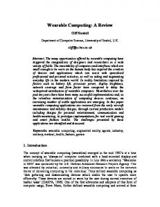
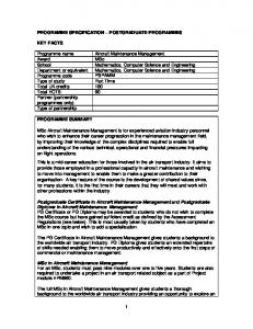
have consequences for the layout of elements on the screens. Second, the use of colors is different on both displays. A light background color is recommended for hand-held interfaces, but might be blinding on a HMD. A third difference is the size and the resolution of the screens. This might simply result in the use of different font sizes, but might also have an influence on the amount of information that can be put on a single screen. Apart from differences in the displays, the interaction methods with these displays are also different. With pen interfaces, the selection and operation of arbitrary areas on the screen can be facilitated. Data gloves for wearables, in contrast, are usually not used for such fine-grained, two-dimensional selection tasks. Problems are that the interaction is not done on a fixed surface, but in free space, and that interaction becomes a secondary task,1 to name just a few. To solve the problem of having two fundamentally different user interfaces for one application, an abstract user interface layer (AUI) was developed, which separates the application from the two different UIs. The two concrete UIs could then be realised independently from each other. Figure 1 gives an overview.
Fig. 1. Architecture overview for the user interfaces of the maintenance application. At the top, there are two independent user interface implementations, each with specific in- and output devices. The UIs are separated from the application by an abstract UI (AUI) layer. The AUI provides two interfaces, one for an application, another for a UI.
To speed up development of future wearable computing applications, the UI part is separated in the so-called WUI-Toolkit [21]. The toolkit provides a mechanism to build new UIs as needed with reusable components in a fast and abstract way. In the future, we plan to implement a speech interface among others. The remainder of this section describes the AUI layer as well as the concrete hand-held and wearable UI implementations.
1
Compared to hand-held computers, wearable computers do not fully occupy the user’s hands. Thus they can be used during another real-world task (primary task).
3.1
Abstract UI Layer
An important aspect in the design of the AUI is that the representation of the UI elements should be independent of any concrete UI. Therefore, the AUI does not contain objects like buttons or windows, which are common in graphical UIs, but that would not be suited to describe elements in other interfaces, e.g. speech interfaces. Abstract UI elements The elements to represent information and interface elements with the AUI are more reduced than in many other UI toolkits. There are six elements available to applications: Item: An item represents an atomic piece of information to be presented to the user. It might contain text data, but also multimedia content (image, sound, video) and might also be composed of alternate data parts. Thus, an application might keep different representations of a piece of information ready (e.g. image and sound) for the interface to select the most appropriate. Group: Groups are used to structure information and contain other elements (also other groups). A concrete UI might represent it as a bevelled border around a number of elements. Depending on the screen space, it might also be represented as a button, that, when pressed, brings up a new dialog showing the content of the group. Trigger: A trigger represents an explicit action by the user. Typically, actions that change data (e.g., “save file”) are realized by triggers. List: A list is composed of a set of items and a set of triggers which can be applied to the items in the list. Selection: The selection element represents a multiple choice input field. The user can choose one or multiple values of a predefined set. Textinput: The textinput element is used to input free text. Depending on the concrete UI, a real keyboard, an on-screen keyboard, or another mechanism might be used. Continuous data model Depending on the concrete output device, a specific amount of information can be presented to the user at a time. A HMD might permit to display more information than the display of a PDA. A speech only interface might even be more reducing. The AUI aims to make the programming of an application independent from that amount of information. Through the AUI, a concrete UI pulls information from the application until it has filled the capacity of information that can be displayed at a time. The pull mechanism is a fine-grained transfer of user interface elements, which means that the UI asks iteratively for the next piece of information. So the UI controls whether it can display more or not. Apart from the information pull, it is also necessary that an application can push information to the UI to update changing pieces of information (e.g. sensor data). Nevertheless, the primary mode of operation of the AUI is the information pull. As a consequence, there exist no major entities like dialogs or frames in the AUI
to define a static composition of basic elements. Instead, the programmer uses groups to indicate the coherence of a number of elements. It is up to the concrete UI to decide how many groups to present to the user at a time. Since the data of an application is usually not static and known a priori, the instanciation is also driven by the AUI. APIs The AUI exposes two APIs to developers (see figure 1). The Application Interface on the one hand is used for the development of applications. The AUI elements described above are used to communicate data between the AUI and the application. The UI Interface on the other hand can be used to develop new user interfaces. 3.2
Hand-held UI
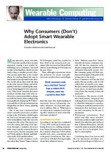
To use the maintenance application on a hand-held display with pen-input, a corresponding interface was developed using the mentioned UI Interface of the AUI. It was implemented using the Java Swing toolkit, resp. the Java AWT. To fill the screen of a typical hand-held computer, it uses the following strategy while recursively processing items from the application (compare figure 2(a)):
(a) Hand-held UI
(b) Wearable UI: the menu on the right can be navigated with a data glove. Currently, “Write Repair Report” is in focus of the selection.
Fig. 2. Screenshots of hand-held UI and wearable UI for the same logbook entry
– Groups on the top level are represented by a typical bevelled border with a text string as the title. The content is placed inside the border and treated as second level content.
– Groups on the second level are represented as headlines. The content is placed below the headline and is treated as third level content. – Groups on the third level are represented as buttons. The content is not shown immediately. If the button is pressed, a new screen is rendered with the content of the group starting on the top level. – Other elements are presented straight forward with no variations depending on their position. This mapping is already sufficient to produce a plain user interface as it is needed for the maintenance application. 3.3
Wearable UI
The graphical components of the wearable UI (WUI) are designed for the MicroOptical SV-6 monocular HMD. The display provides VGA resolution, a narrow field of view of approximately 16 degrees horizontal and 20 degrees diagonal, and is relatively small compared to a desktop display. It is expected to be worn out of the visual center, i.e. on the right side on the right eye or on the left side on the left eye, so the user can primarily focus on the real-world task. When the display is placed as described, there are areas on the display, which are more in the visual center and others being more in the periphery. For the WUI developed so far, we considered only wearing the display in front of the right eye. Then, the left part of the screen is more in the visual center than the right part and thus more comfortable to see. For this reason, we added some empty space on the right margin of the interface that causes the whole interface to move more to the left and thus more to the visual center of the user’s eye. For left-eye usage, the situation is reversed. The elements on the screen are arranged to take this situation into account. A two-column layout is chosen to take advantage of the situation. The important content – e.g. defect descriptions and troubleshooting instructions – is placed in the left column. As described in the previous section, we reduced interaction to a one-dimensional process. In the graphical interface, this is reflected by interacting with a vertical list of items in the second column on the right side of the screen (see figure 2(b)). The content column on the left is arranged vertically. Borders are used to create groups of elements. Multiple pages arrange content into blocks fitting on the screen. Visual elements connect specific parts of the content on the left to menu items on the right to express coherence, e.g. the content text “Location: Cabin Zone, 17 E-F” is connected to the menu item “Area List”. A history function is automatically added by the WUI-Toolkit at the bottom of the screen that provides navigation to previous and next dialogues. In contrast to desktop screen design, a dark background color was chosen (dark blue) with bright foreground colors (white and yellow). On a HMD dark colors tend to be perceived as being transparent. A bright background might blind the user. Large fonts (20 pixels) are chosen for comfortable reading on the small display.
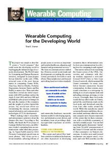
Fig. 3. Gestures for interaction
Interaction Method Used For hands-free control of the application we use a wireless data glove. The data glove comprises a tilt sensor for the recognition of gestures and three magnetic switches. A RFID reader in the glove is used to identify tagged components in the aircraft. See [11] for details. The interaction style supported by the current version of the UI is menu selection [22]. Three different gestures have been defined to control the cursor. Compared to direct manipulation techniques, gestures only require low visual attention [23]. To navigate forth and back through the vertical list menu structure, we use intuitive hand-based rotation gestures (see figure 3). Navigating back in the menu structure to select a previous item is done by turning the hand to the right and back to the starting position. To navigate forth in the menu structure and select the next item in list the starting motion is a left turn. A third gesture similar to a mouse click was used for selecting items. It is performed by touching the middle finger with the thumb and recognized by a magnetic switch in the glove.
4
Clothes Integration
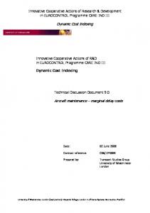
Although devices for wearable computing have become much smaller in recent years, the necessity of a comfortable placement of these devices on the body is still an issue. Wireless technologies such as Bluetooth have simplified the donning of wearables. However, sophisticated clothes to hide the remaining cables are still needed. The maintenance wearable includes a vest housing the computer and accessories as well as a data glove with sensors to interact with the computer. The vest was designed to house all components of the wearable except the data glove, which is worn separately. Thus, a technician does not need to worry about the correct cabling or whether a component is missing. Moreover, the parts are protected from dirt. The devices of the wearable system in the vest are: MicroOptical SV-6 HMD with controller box and battery, OQO personal computer, and a Bluetooth keyboard. The OQO and HMD are connected by a wire, the keyboard connects wirelessly. The OQO computer has a built-in touchscreen with pen input. While this interface is not used in combination with the HMD, it can be used as an alternative to the HMD. Depending on the task at hand, either interface might be preferred by the user. The vest has to support the change of the interaction mode: in wearable mode, the OQO is worn on the body, its internal
(a) When the vest is closed, the computer can be used with HMD and data glove.
(b) Opening the vest is automatically detected and the mode of interaction is changed to pen input.
Fig. 4. Vest for maintenance personnel housing all components of the wearable computer
display is not visible, and the HMD is active. In hand-held mode, the device is used in the user’s hand. It would be too complicated and error-prone to detach the OQO from the wire to the HMD. An extension of the vest is detachable while all cables stay connected, thus protecting the cables and preventing the device from falling down. Figure 4 illustrates the design. To automatically adapt its user interface, the computer needs to detect, whether it is attached or in the user’s hand. A magnetic switch integrated into the attachment incorporates this function.
5
Semantic Structuring of Maintenance Data
In order to support the work of the maintenance technician, a knowledge management component clusters defect messages and stores maintenance experience in form of repair reports according to the messages. For a given message, the knowledge management component searches similar former messages and shows the technician the repair reports related to these messages with a ranking of relevance (see [2]).
Architecture To achive the necessary functionality, the knowledge management component is based on the KnowWork ontology engine (called domain model; see [19]) and the Apache Lucene text retrieval engine. On top of these components three knowledge management systems are established (see figure 5). 1. The first knowledge management system is installed in an aircraft and stores the detailed product structure of that particular aircraft. This information is needed to calculate the structural proximity of two defects (see [2]). Based on this data, defect reports which are possibly related, can be clustered. 2. A second system is installed on the wearable of a technician. This system contains the whole experience knowledge of a maintenance company in form of repair reports and the defect messages. The system connects to the electronic logbook of the aircraft and imports all defect reports. Furthermore, this system connects to the above knowledge management system in order to access the product structure data. 3. The third system stays on the ground in the airport and collects all new defect reports and repair reports.
Aircraft Server
Toolbox Server
Ground Server
KMS
KMS
Expirience Knowledge
Expirience Knowledge
Logbook
KMS
Product Data
Fig. 5. Architecture overview for the knowledge management systems and their interaction
The different knowledge management systems are communicating via Web services with each other. The electronic logbook is also accessible by a Web service. The whole accumulated experience knowledge will be stored within the so-called ground server. If a technician checks a new aircraft, he first has to synchronize the wearable’s knowledge base with the ground server. When a technician returns from a maintenance job the new knowledge in the form of defect and related repair reports is copied to the ground server, so that the new knowledge is available for other technicians (see [2] for a detailed workflow description). Domain Model Because of the usage of the KnowWork domain model, the capabilities of this system are used to develop the specific ontologies. The KnowWork model delivers the typical relations is-a and has and furthermore a relational concept called class reference. With a class reference, an attribute of an
instance refers to a concept instead of to another instance. The product structure ontology is devided into two parts, the so-called model view, which is equal in all aircrafts of the same type and the airplane specific instance view, which describes the exact construction of a particular aircraft. The documentation is part of the model view and assigned to the related models. With the knowledge about the structure of an aircraft, the system has the opportunity to cluster defects, which are possibly related to each other because of the structural proximity. The structural proximity is defined as the number of nodes between two parts within the product structure tree. If there are two defects assigned to two parts with close structural proximity, it is possible that these two defects are related. For instance, the aircraft diagnostic system stores a message in the logbook that a transformator is defect and a flight attendant reports a defect reading light. The structural proximity of these two parts might be close, because the parts are connected directly by a wire. So the two defects have a good chance of being related, and so the system will cluster these defects. The technician will see this information directly on the defect list. Each defect report has a specific defect description and a relation to a repair report. A defect report is entered into the electronic logbook by the cabin crew. The knowledge management system on the wearable imports this report and creates a defect report in its knowledge base. If the defect is repaired, a relation to the repair report will be established. Furthermore a model of defects is designed as a is-a concept hierarchy. Defects have a relation as class reference within the defect concept tree. So it is possible to navigate through the tree and to see, which concrete defects are assigned to the actual tree nodes and which defect reports are assigned to them. Text retrieval In the similarity search index, the defect report texts are stored in relation to the defect report numbers. So, when similar defects are searched by the user, the system delivers a set of defect report numbers ranked by similarity. Each of the related defect reports in the domain model has a relation to a repair report. With this relation, it is possible for a user to access repair reports to similar defects as a given one. So it is possible to access the knowledge of former technicians, who have repaired similar defects by reading their reports. If these reports do not help the technician, he can see at least who has experiences with defects like the actual one.
6
Conclusion and Future Work
In this paper, we presented results from the ongoing work of the implementation of a wearable computing solution for aircraft maintenance. The focus of the project is not on a single technology, but on combining several components and proving the feasibility of the wearable computing solution. In particular, focus was put on the representation of and reasoning over the maintenance data, the user interface, and clothing aspects. To enable powerful mechanisms for browsing the maintenance data, a knowledge
management system is used to represent product data of the aircraft as well as defects. Additionally, a similarity search system helps to detect relations between defect reports. For the user interface, an abstract UI layer was developed to decouple the application from the concrete interface. Using this approach, two UIs were developed which can be used alternativlely by the user: A pen interface for hand-held mode and a wearable UI. The wearable UI is displayed on a HMD and operated by gestures with an unobtrusive data glove. The aspect of wearing comfort of the system is addressed by a specially designed vest housing all components and enabling a quick switching of the user interface. When the project started, a PDA was targeted as a platform. Additionally, a notebook running the knowledge management system was planned to be built into the toolbox of the technician. With the advent of smaller and more powerful computers, like the OQO, we decided to abandon the PDA platform as well as the notebook in the toolbox in favor of using the OQO for both tasks. The next step in the project will be the evaluation of the protoype. First, we plan to conduct a workshop with users to get initial feedback. Then the prototype will be evaluated in a real maintenance setting. The WUI toolkit will ease the future development of other wearable computing applications. Acknowledgements This research was funded by the German Bundesministerium f¨ ur Wirtschaft und Arbeit (BMWA). The authors would like to thank Nils Behrens, Christoph Breckenfelder, Burcu Cinasz, Jan-Christoph Ebersbach, Ulrich Glotzbach, Andreas Kemnade, R¨ udiger Leibrandt, Olena Rohovets, Heidi Thielemann, and Xin Xing for their indispensable contributions to this project.
References 1. Stein, R., Ferrero, S., Hetfield, M., Quinn, A., Krichever, M.: Development of a commercially successful wearable data collection system. In: ISWC ’98: Proceedings of the 2nd IEEE International Symposium on Wearable Computers, Washington, DC, USA, IEEE Computer Society (1998) 18 2. Nicolai, T., Sindt, T., Kenn, H., Witt, H.: Case study of wearable computing for aircraft maintenance. In Herzog, O., Lawo, M., Lukowicz, P., Randall, J., eds.: 2nd International Forum on Applied Wearable Computing (IFAWC) 2005, VDE Verlag (2005) 97–110 3. Mizell, D.: Boeing’s wire bundle assembly project. In Barfield, W., Caudell, T., eds.: Fundamentals of wearable computing and augmented reality. Lawrence Earlbaum Associates, New Jersey (2001) 447–467 4. Willers, D., Regenbrecht, H.: ARVIKA Abschlussbericht. Technical report, Airbus Deutschland GmbH, Hamburg, Germany (2003) 5. Beu, A., Hassenzahl, M., Quaet-Faslem, P., Burmeister, M.: Benutzerzentrierte Gestaltung eines mobilen Service- und Wartungssystems unter Verwendung von AR-Technologie. MMI-Interaktiv Journal (2001) 6. WearIT@work Project: An integrated project in the sixth framework programme. http://www.wearitatwork.com (2006) accessed January 20th 2006. 7. Starner, T.: The challenges of wearable computing: Part 1. IEEE Micro 21 (2001) 44–52
8. Clark, A.F.: What do we want from a wearable user interface? In: Workshop on Software Engineering for Wearable and Pervasive Computing, Limerick, Ireland (2000) 3 9. Bass, L., Kasabach, C., Martin, R., Siewiorek, D., Smailagic, A., Stivoric, J.: The design of a wearable computer. In: Conference on Human Factors in Computing Systems (CHI ’97), ACM Press (1997) 10. Schmidt, A., Gellersen, H.W., Beigl, M., Thate, O.: Developing user interfaces for wearable computers: Don’t stop to point and click. In: International Workshop on Interactive Applications of Mobile Computing (IMC2000), Warnem¨ unde, Fraunhofer Gesellschaft (2000) 11. Boronowsky, M., Nicolai, T., Schlieder, C., Schmidt, A.: Winspect: A case study for wearable computing-supported inspection tasks. In: Fifth International Symposium on Wearable Computers (ISWC ’01). Volume 5., IEEE Computer Society, IEEE Computer Society (2001) 163–164 12. Schneider, L.: Formalised elementary formal ontology. Isib-cnr internal report 3/2002, Institute of Cognitive Sciences and Technology (2002) 13. Baader, F., Nutt, W.: Basic description logic. In Baader, F., Calvanese, D., Guiness, D.M., Nardi, D., Patel-Schmidt, P., eds.: Description Logic Handbook. Cambridge University Press (2002) 14. Maedche, A., Motik, B., Stojanovic, L., Studer, R., Volz, R.: Ontologies for enterprise knowledge management. IEEE Intelligent Systems, January/February 2003 (2003) 15. T¨ onshoff, H.K., Apitz, R., Lattner, A.D., Schlieder, C.: Knowwork - an approach to co-ordinate knowledge within technical sales, design and process planning departments. In: Proceedings of the 7th International Conference on Concurrent Enterprising, Bremen, Germany (2001) 231–239 16. Horrocks, I.: Using an expressive description logic: FaCT or fiction? (1998) 636–647 17. Haarslev, V., M¨ oller, R.: Practical reasoning in racer with a concrete domain for linear inequations. In: Proceedings of the International Workshop on Description Logics (DL-2002), Toulouse, France, April 19-21. (2002) 91–98 18. McBride, B.: Jena: Implementing the rdf model and syntax specification. In: SemWeb. (2001) 19. T¨ onshoff, H.K., Apitz, R., Lattner, A.D., Sch¨ affer, C.: Support for different views on information in concurrent enterprises. In: Proceedings of the 8th International Conference on Concurrent Enterprising, Rome, Italy (2002) 143–150 20. T¨ onshoff, H.K., Apitz, R.: Ontology-based knowledge management for the product development process. Machine Engineering 2 (2002) 33–39 21. Witt, H.: A toolkit for context-aware wearable user interface development for wearable computers. In: ISWC’05: 9th International Symposium on Wearable Computing, IEEE (2005) 22. Shneiderman, B., Plaisant, C.: Designing the user interface: strategies for effective human-computer interaction. Addison-Wesley Longman Publishing Co., Inc., Boston, MA, USA (2005) 23. Witt, H., Nicolai, T., Kenn, H.: Designing a wearable user interface for hands-free interaction in maintenance applications. In: PerCom’06: Proceedings of the 4th annual IEEE International Conference on Pervasive Computing and Communications, Pisa, Italy, IEEE Computer Society (2006)