Laurent Balmelli, Gabriel Taubin, and Fausto Bernar- dini. Space-optimized texture maps. In George Dret- takis and Hans-Peter Seidel, editors, Proceedings Eu-.
4th International Symposium on Virtual Reality, Archaeology and Intelligent Cultural Heritage (2003), pp. 1–12 D. Arnold, A. Chalmers, F. Niccolucci (Editors)
Web-based visualization of virtual archaeological sites Markus Grabner1 , Ralph Wozelka1 , Manish Mirchandani2 , Konrad Schindler1 1 Computer 2 Computer
Graphics and Vision, Graz University of Technology, Graz, Austria Science and Engineering, Indian Institute of Technology, Bombay, India
Abstract We present a web-based visualization tool for archaeological sites that has been developed within the 3D Murale project. The problem of structuring the scene prior to visualization is addressed by an extension to the 3D modeling and animation package MayaTM which enables communication with the common data pool of 3D Murale. Texture data is prepared for visualization by encoding it using the JPEG 2000 standard, which is based on wavelet technology and allows easy access to encoded images at different resolutions. Finally, we provide an ActiveX plugin for the Microsoft Internet Explorer to enable convenient exploration of the archaeological scene in a web environment. Our approaches are demonstrated using a model of a frieze of dancing girls (Sagalassos, southwest Turkey). The discussion of our methods is supported by performance data and screen shots. Categories and Subject Descriptors (according to ACM CCS): I.3.8 [Computer Graphics]: Applications
1. Introduction The application of computer graphics and 3D data acquisition methods in archaeology has recently gained much attention. This is mainly due to the huge amount of geometry and image data one has to deal with when describing an archaeological excavation site. The excavation site is continuously being modified as the excavation proceeds. Therefore it is particularly important to record the current state of the site at regular intervals to make validation of the scientific conclusions possible. An efficient and reliable acquisition process is desirable since the time the archaeologists are interrupted in their field work should be minimized. However, increasing resolution and speed of the acquisition methods also results in more data being produced. Sharing these data with colleagues and other interested people all over the world requires sophisticated techniques for storage, transmission, and visualization.
a database. This serves as common data pool for all involved data acquisition, management, and visualization processes. • Much work has been done on compression, progressive transmission, and view-dependent visualization of geometry data. We show that the JPEG 2000 image format can be used to achieve similar effects for texture data. • Our visualization tool is implemented as a browser plugin (based on WebCAME18 ), with particular attention paid to typical navigation styles in the context of virtual archaeology. The paper is organized as follows. In Section 2 we review some previous work in the related fields of research. Sections 3, 4, and 5 deal with the abovementioned contributions. Examples, results, and screenshots are presented throughout the paper where appropriate. The paper is concluded in Section 6.
We improve previous work24, 18 and propose solutions to three problems in this context: • Gathering data from different sources and arranging them in correct geometric relation to each other requires a powerful graphical user interface. We use Maya for this purpose and extend it to enable direct communication with c The Eurographics Association 2003.
2. Related work Since our work addresses different topics in the wider context of virtual archaeology, we can only give a brief overview of the relevant areas.
Grabner, Wozelka, Mirchandani, Schindler / Web-based visualization of virtual archaeological sites
2.1. Virtual archaeology projects An important goal of virtual archaeological projects is the enhancement of the user’s experience of the site. In the ARCHEOGUIDE project28, 36 , the user is equipped with mobile devices such as Head-Mounted Displays to provide context-sensitive explanation of the site as he or she walks around. The 3D Murale project12 aims at the measurement, reconstruction, and visualization of archaeological excavation sites. In addition to an accurate geometric model of the site (which is also required in ARCHEOGUIDE for registration of the real and virtual worlds), a well-structured scene with properly assigned meta data is crucial in 3D Murale since the system is intended for documentation purposes. Other activities in this area are more concerned with behaviour than geometry. The TOURBOT system31 allows the user to navigate a robot through a museum and to receive images captured by a camera mounted on the robot. Intelligent virtual humans populate the scene in the CHARISMATIC project4 . 2.2. Scenegraph concepts Many graphics APIs and applications make use of different flavours of the scenegraph concept. One of the first of its kind was Open Inventor38 , an object-oriented 3D graphics library for C++. This served as the basis for the popular VRML language37 . Commercial products such as Maya and similar tools also make use of a hierarchical scene description. Design choices and their implications are discussed in Section 3. Recent trends in scenegraph development aim at large model visualization. High-level algorithms such as mesh reduction and occlusion culling are integrated into the Jupiter toolkit6 . A flexible and extensible framework for scenegraph traversal29 has been presented to meet specific application requirements regarding traversal order.
algorithms have been extended to support view-dependent operation22 . This is particularly important for large meshes (such as terrain models), where the user is only interested in a small portion of the whole data set. External memory methods15 are becoming increasingly important since recent reconstruction techniques generate meshes too large to fit into main memory. Other mesh attributes such as color and normal vectors10 or texture parametrization33, 14 are taken into account to improve the perceived quality of the mesh. The field of mesh compression has been pioneered by the introduction of the generalized triangle mesh13 . In the following years, several methods have been proposed that further improve compression ratio35, 30, 3 . Progressive compression is particularly important for applications involving suboptimal transmission of mesh data (e.g., standard internet connections). Hoppe23 recognized that progressive mesh simplification supports compact encoding, which was further elaborated by Pajarola and Rossignac27 . Other approaches have been recently proposed11, 2 , including a wavelet-based solution26 . The CAME data structure17 , which is the core of our client/server architecture, has been introduced to reduce the storage requirements of the original meta-node approach15 . A compression ratio of approximately 1:25 has been achieved compared to the uncompressed meta-node data, still providing view-dependent access to multiresolution triangle meshes of arbitrary topology. It has been extended by an adaptive quantization method with error control20 . Often the bottleneck of client/server visualization systems is the network connection between the involved machines. Progressive transmission techniques aim at optimally utilizing the available bandwidth to provide the user with the relevant data for the current view. Such methods have typically been developed in the context of multiresolution and/or compression techniques such as those mentioned above.
Archaeology-specific extensions to the classical scenegraph concept have been proposed24 for the use within the 3D Murale multimedia database16 .
A completely different approach, avoiding any explicit representation of a continuous surface, uses a hierarchical description of a point cloud, typically sampled from the original surface32 .
2.3. Processing of large 3D scenes
2.4. Web3D applications
As explained in Section 1, huge geometric data sets are involved in virtual archaeology applications. Processing of these data includes compression, transmission, and visualization.
Several commercial products exist (e.g., MetaStreamTM by Abadjev et al.1 ) to provide the methods discussed in Section 2.3 in the web context. Other research work deals with mesh encoding using ASCII25 , optimizing the transmission sequence34 , and adapting to the available bandwidth8 .
The representation of geometric objects at different levels of detail has first been studied by Clark9 in the context of visible surface algorithms. More sophisticated methods compute a fine-grained multiresolution representation of the input mesh. The Progressive Meshes approach21 is a popular method of this kind. To account for the user’s varying location and viewing direction within the scene, multiresolution
In previous work, we have developed a prototype web environment based on CAME (WebCAME18 ) for the Mozilla web browser on the Linux operating system. To allow smart interaction with objects in the scene, we demonstrated how to identify individual objects in a view-dependent multiresolution framework19 . A similar approach is presented in this c The Eurographics Association 2003.
Grabner, Wozelka, Mirchandani, Schindler / Web-based visualization of virtual archaeological sites
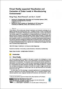
Figure 1: Screenshot of Maya, depicting a frieze of dancing girls originally belonging to the upper part of the socle of the Augustan northwest Heroon of Sagalassos in southwest Turkey
paper, with improved texture support (Section 4) and increased focus on usability (Section 5). 3. Scene management
some classical scenegraph concepts (Inventor, VRML). Advanced features for large model visualization (such as those provided by the Jupiter toolkit6 ) are currently not considered in this project.
As mentioned in the introduction, convenient manipulation of 3D scenes and data exchange are crucial issues to achieve proper usability. We chose the Maya 3D modeling environment, which has been extended to support database access and can be used to edit scenegraphs stored in the 3D Murale database. We offer data exchange facilities supporting Inventor and, along with Maya, VRML export.
3.1.1. Open Inventor
3.1. Scenegraph concepts
3.1.2. VRML 97
In the following, a short description of relevant scenegraph concepts is given including the 3D Murale scenegraph format used in the database. This is followed by a brief overview of how 3D data is mapped to the 3D Murale scenegraph format.
The solution originally proposed24 is conceptually similar to VRML. It was observed that most of the transformations in the scene are used to place groups of objects into the correct place in space. This led to the decision to assign transformations to connections (or arcs) between nodes (instead of using an additional node for each transformation) to reduce the total number of nodes. This is equivalent to VRML,
The main objective here is a proper association of attributes and nodes. We therefore restrict the discussion to c The Eurographics Association 2003.
Some of the reconstruction tools of the 3D Murale project are based on Open Inventor. We therefore use this powerful open source library provided by SGI as an interface to these tools. In Open Inventor, transform nodes affect all right siblings and their subgraphs (gray nodes in Figure 2(a)), they do not have children on their own.
Grabner, Wozelka, Mirchandani, Schindler / Web-based visualization of virtual archaeological sites
T
T
T
(a) Open Inventor
(b) VRML
G
G
T
G
G
(c) Maya
T
TG
G
T
(d) newly proposed model for 3D MURALE
Figure 2: Different scenegraph concepts, nodes affected by the transformation are shown in gray
where the transformation node is a group node affecting all children nodes below it (Figure 2(b)), so transformations are inherited top-down. Readily available plugins of Maya add VRML97 support to our database export capabilities.
3.1.3. Maya Maya uses a scenegraph concept which is basically similar to VRML. Transform nodes are used to group objects, and their transformation is inherited by all child nodes. Each transform node can have multiple other transform nodes as children, but (in contrast to VRML) only a single shape node (see Figure 2(c)). The scenegraph in Maya is composed of nodes which store node specific data as attributes. Transform and shape nodes are special nodes with transformation and geometry attributes. Additionally, Maya offers the possibility to add arbitrary attributes to instances of DAG nodes, which is necessary within the 3D Murale project to store archaeological meta data (see also Section 3.2.3).
Maya T
3D Murale
unit
T
T T
unit
G
G T G
T
G Figure 3: Mapping of Maya to 3D Murale scenegraph, geometry nodes/attributes are denoted by “G”, transformation nodes/attributes by “T”
3.1.4. Scenegraph concept in 3D Murale 3.2. Database mapping Our concept is similar to the one used in Maya, except for one simplification: in the 3D Murale scenegraph transformation and geometry are optional attributes of a generic node type instead of being separate nodes. A missing geometry attribute implies no shape being available at this node, and a missing transformation attribute is equivalent to a unity transform (see Figure 3). The benefit is to further reduce the total number of nodes, which allows a more efficient storage in the database. The structure is compatible with Maya and enables a complete mapping of the scenegraph to the database. Therefore the Maya user interface does not need to be restricted with respect to scenegraph editing. See Figure 1 for an example of an archaeological scene opened in Maya.
The database model reflects the 3D Murale scenegraph concept of Section 3.1.4. The new model improves the previously presented one24 in the following ways: • There is no distinction between different node types, instead each entity is represented by an instance of a unified node object with optionally assigned attributes (see Figure 3). • The hierarchical structure is defined by a table of arcs, with each arc identifying its source and destination node. Transformation data as well as geometry data are stored in related tables and are indexed using the corresponding node’s id, which allows for efficient database queries. The Maya customization for database access was done by dec The Eurographics Association 2003.
Grabner, Wozelka, Mirchandani, Schindler / Web-based visualization of virtual archaeological sites
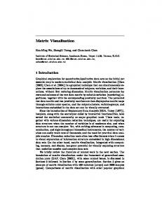
(a) JPEG (level 2, 8970 bytes)
(b) JPEG 2000 (level 3, 8446 bytes)
Figure 4: Comparison of JPEG and JPEG 2000 after similar amounts of progressively transmitted data
veloping a plugin using the Maya C++ API, which allows convenient access to scenegraph data. Maya GUI customizations are based on the Maya specific MEL scripting language. SQL database access is done using the ODBC interface. The Open Inventor format is supported through command line tools, which make use of the Open Inventor toolkit to access scenegraph data. These tools are available for the Linux and Microsoft Windows platforms. 3.2.1. Scenegraph The scenegraph structure is transformed to and from the database by converting shape and geometry nodes into the corresponding database attributes according to Figure 3. Node information (such as names of the represented object or group of objects), arcs of the scenegraph, transformation, and geometry information are each stored in their own table. While the Open Inventor import tool is used to process data from the reconstruction tools, the corresponding export tool is a convenient interface to our multiresolution preprocessor which also operates on Inventor scenegraphs. Thus writing the file to disk is avoided. 3.2.2. Polygon meshes In contrast to the Open Inventor and VRML data structure, Maya explicitly deals with polygon edges (in addition to vertices and faces). To speed up the conversion from the 3D Murale to the Maya structure, we also store edges in the database. Polygons refer to edges (instead of vertices), where the edge index is positive for an edge with counter-clockwise c The Eurographics Association 2003.
orientation along the polygon’s boundary, and negative otherwise. 3.2.3. Application-specific attributes The mechanism of optional attribute assignment can also be used to define other application-specific properties, such as the period of time during which a building existed, and the level of confidence of the archaeological reconstructions. This can be implemented without overhead in the node structure by a table for each attribute type, containing the attribute value and the key of the node this attribute belongs to. 4. Progressive texture transmission Several methods have been developed to progressively compress (and transmit) geometry. In many applications (and especially in a web environment) texture data is as important since it improves realism of the renderings without having to describe scene geometry in full detail. However, progressive transmission of texture data has not yet been taken into account in the context of progressive compression of arbitrary meshes. 4.1. JPEG 2000 The JPEG data format is a common choice for storage of texture data. However, it provides only limited facilities for progressive transmission (sometimes used on web pages). Moreover, the annoying blocking artefacts that appear under high compression make the JPEG file format less suitable for our purposes. The recently developed JPEG 2000 format, which is based on the wavelet principle, solves the abovementioned problems. In particular, it provides:
Grabner, Wozelka, Mirchandani, Schindler / Web-based visualization of virtual archaeological sites
(a) JPEG
(b) JPEG 2000
(a) level 1
(b) level 2
Figure 5: Detailed view of the area around the left shoulder of the dancing girl depicted in Figure 4 after fully decoding the image
• Convenient progressive access to the image data • Reasonable image quality even at high compression • Best compression ratio currently available for photographic images JPEG 2000 offers some additional useful features, which, however, are not yet exploited in our current implementation: • Image tiling can be used to decompose very large texture images into independently processed parts. • Regions of interest allow to specify areas in the image that should be stored and transmitted at higher quality than the remaining image. Note that the space-optimized texture maps approach5 also solves the problem of representing images at varying detail. However, it does so at the cost of a reparametrization. This would make transmission of texture coordinates necessary, which is expensive in terms of transmission time. 4.2. Comparison of JPEG and JPEG 2000 We demonstrate the difference between the two image compression standards by means of a texture image (1024×1024 pixel) from Figure 1. The image decoded after transmission of a little more than 8kB is shown in Figures 4(a) and 4(b) for the JPEG and JPEG 2000 method, respectively. Due to the 8 × 8 block size restriction of the JPEG method we clearly identify small blocks in Figure 4(a). This becomes particular obvious in the magnification in Figure 5(a). Moreover, the method fails to heavily compress the image at its lowest resolution, resulting in more than 6kB for representing the first level of the image. On the other hand, JPEG 2000 compresses the image to less than 2kB for the lowest resolution (Figure 6(a)). While this image appears quite blurred compared to the original image, it is still sufficient if applied to an object that only
(c) level 3
Figure 6: Progressive image loading using JPEG 2000
occupies a small fraction of the total screen area. As more and more data is received, the image approximates the original image and is almost indistinguishable from it in Figure 6(c). JPEG 2000 defines different progression orders (see Table 1) to specify which properties of the image should be retrieved first. For example, the CPRL order allows the image to be retrieved in grayscale at full resolution before color gets merged into it. For our purposes, the default LRCP procedure is sufficient, illustrated in Figures 6. The storage requirements for the test image in Figure 4 are given in Table 2. Note that the code stream both for JPEG and JPEG 2000 has a three times finer granularity than indicated by the levels in the table, which is due to the existence of three color channels. However, we do not make use of this since visible differences only appear after transmission of three image components due to the use of the PCS XYZ color space7 . Several notes apply to the test image in Figure 4: c The Eurographics Association 2003.
Grabner, Wozelka, Mirchandani, Schindler / Web-based visualization of virtual archaeological sites
Value
Description
lrcp
layer-resolution-component-position (LRCP) progressive (i.e., rate scalable)
rlcp
resolution-layer-component-position (RLCP) progressive (i.e., resolution scalable)
rpcl
resolution-position-component-layer (RPCL) progressive
pcrl
position-component-resolution-layer (PCRL) progressive
cprl
component-position-resolution-layer (CPRL) progressive
Table 1: JPEG 2000 progression orders and the corresponding parameter value for the prg option in the Jasper software
method
quality
level 1
level 2
level 3
level 4
total size
uncompressed TIFF
N/A
N/A
N/A
N/A
N/A
3145932
JPEG
10%
6123
8970
12244
22154
22154
JPEG 2000
N/A
1658
3928
8446
16374
22008
Table 2: Storage requirements for different levels of progressively encoded image, sizes are given in bytes
• There is a slight distortion to meet the graphics hardware’s requirement for quadratic texture images. • We have used higher compression ratio (i.e., smaller size of encoder output) than what is suitable for rendering in the real application. This is to make the resulting artefacts easier to observe and therefore both methods easier to compare. • If the storage size of the first level of an image (as in Figure 6(a)) is still too large, the number of resolution levels (which defaults to six in our software) can be further increased. This gives even coarser (and smaller) images to start with. 4.3. Header compression The JPEG 2000 code stream is divided into segments, which are identified by unique markers. While the segments following the SOD (start of data) markers contain highly compressed image data, the segments describing the content of the image (e.g., width and height of image, color space, etc.) allow for some additional compression. The CME segment (“comment and extension”) holds an optional image description text and can be entirely omitted since it does not contribute to the image itself. Although this header information is small compared to the size of the complete (JPEG 2000 encoded) image, it is desirable to load it as efficient as possible to preallocate resources (e.g., texture space on the graphics card). We use a combination of run length encoding and Huffman encoding with a fixed code alphabet reflecting the frequency of characters in a typical JPEG 2000 header. In table c The Eurographics Association 2003.
method
raw data
gzip
bzip2
ours
size in bytes
144
109
107
64
Table 3: Compression performance of different methods for JPEG 2000 header data (after removing the “comment and extension” segment)
3 our method is compared with the general-purpose compression tools gzip and bzip2. Due to the use of a priori knowledge about the data, our algorithm performs significantly better than the other two methods. 4.4. Asynchronous retrieval Following the 3D Murale open source approach, we decided to use the free JasPer library for providing JPEG 2000 functionality. Due to the design of this library, image data can not be directly decoded into texture space. However, since all texture operations except rendering are performed in a separate thread, this only causes some delay until the texture is available. It does not slow down rendering of the scene in a noticeable way. We follow previous approaches of multithreaded operation15, 17 and extend this concept also to handle texture data. Requests for texture and geometry data are queued in two separate buffers by the rendering thread. The corresponding threads process these requests and pass the queries to a (typically remote) database. Rendering is
Grabner, Wozelka, Mirchandani, Schindler / Web-based visualization of virtual archaeological sites
continued while the query threads are waiting for the results of the database queries. As soon as data has been received, the scene is updated, and the modified scene can be used for rendering. See Figure 7 for an illustration.
this navigation sequence (Figure 10). This feature actually plays the role of a shortcut to repeated rotations-translations that need to be done to get the same effect as in this object centered navigation mode.
5. Navigation
5.3. Object examination
A tool has been developed for progressive transmission and visualization of compressed non-manifold triangle meshes over the web. The implementation of this tool is done as an ActiveX plugin based on MFC (Microsoft Foundation Classes) to reach a maximum number of potential users. The plugin is displayed within a Microsoft Internet Explorer window when a web page containing the appropriate OBJECT tag is visited. Rendering is done by means of OpenGL. While the interior design is similar to a previously presented system18 , we focused on meaningful navigation styles both for generic and application-specific use. Figure 8 shows a screenshot of our visualization tool embedded into a web page.
Following the paradigm of a virtual exhibition, the user should also be able to study an object detached from its original context (in addition to getting different views as explained in Section 5.2). When this object examination mode is active, an object selected by the user is moved right in front of the virtual camera, leaving behind the rest of the scene as it is. While the object is “popped up”, it can be rotated to provide otherwise inaccessible views of it. This is the case for object C in Figure 11, which is close to object B and therefore cannot be easily examined in its original location.
5.1. Traditional navigation Several navigation styles are well known from VRML clients such as CosmoPlayer or Cortona. Figure 9 illustrates some traditional navigation styles, with three objects A, B, and C in the field of view of the user. Depending on which mouse button is pressed, the virtual camera is translated (Figure 9(a)) or rotated (Figure 9(b)). The motion of the mouse is directly mapped to the translation value instead of velocity (and similarly to the rotation angle instead of angular velocity in rotation mode). While this reduces the risk of getting lost in virtual world, it makes it difficult to cover large distances, which requires repeated mouse strokes. To alleviate this problem, a seek mode is provided which translates and orients the camera towards a point selected by mouse click (such as object C in Figure 9(c)). To avoid confusion, the camera parameters are not modified instantaneously, but are smoothly adapted to the new values in a so-called seek animation.
Similar to the seek animation discussed in Section 5.1, the selected object is smoothly moved to its new position in front of the virtual camera before it can be examined. Switching off the object examination mode restores the scene as it was before this mode has been entered (again using a short animation). A modified mouse cursor shape reminds the user that mouse input only affects a single object instead of the virtual camera in this mode.
5.4. Terrain following All previously discussed navigation methods assume a walking-like behaviour, requiring a fixed elevation of the virtual camera above ground. The y-value of the camera position is actually computed as y = g(x, z) + d, where d is the desired fixed elevation above ground, and g(x, z) is the ground level below the virtual camera.
5.5. Multiresolution issues 5.2. Object-centered navigation In a virtual environment containing freely accessible objects (such as a virtual archaeological excavation site), the user’s interest is often focused on a single object for some time. However, getting different views of an object is a tedious task using the methods described in Section 5.1. Therefore the object-centered navigation mode is provided, which allows the complete scene to be rotated around the object of interest (object C in Figure 10). More exactly, the rotation axis is chosen parallel to the vertical coordinate axis (the y-axis by OpenGL convention) and containing the center of gravity of the desired object. Note that the angle ϕ under which the selected object appears on screen remains fixed during
While the methods discussed in Sections 5.1 to 5.4 can easily be applied to static scenes, in our application we have to deal with a dynamic scene at varying resolution. This affects the design of our algorithms since not all data required for correct results might be available at the time of computation. This is true at least for the following cases: • In object-centered navigation mode, the user expects to rotate around the object’s center of gravity, which is the mean value of the coordinates of all vertices of the object in the original model. Instead of precomputing and transmitting this value for all objects, we dynamically compute an approximation, taking into account only vertices received so far. c The Eurographics Association 2003.
Grabner, Wozelka, Mirchandani, Schindler / Web-based visualization of virtual archaeological sites
texture request buffer rendering thread
texture thread database
geometry request buffer
geometry thread
scene Figure 7: Multi-threaded geometry and texture retrieval
Figure 8: Screenshot of the same scene as in Figure 1, with compressed geometry and texture, displayed in the Microsoft Internet Explorer
c The Eurographics Association 2003.
Grabner, Wozelka, Mirchandani, Schindler / Web-based visualization of virtual archaeological sites
B
B
B C
C
C
A
A
(a) translation
A
(b) rotation
(c) seeking
Figure 9: Traditional mouse navigation styles, the position and orientation of the virtual camera are modified relative to its initial setting (dashed)
B
B C A
A
ϕ
ϕ C
Figure 10: Object centered navigation
Figure 11: Object examination
6. Conclusions and future work • Exact terrain following requires the fully detailed ground mesh (at least below the virtual camera). This is unlikely to be available due to transmission delays and the fact that the projection center of the virtual camera lies outside the view frustum. Again we use the currently available approximation, which also reduces “jittering” of the camera position if the ground data is noisy.
We presented the 3D Murale internet visualization tool and some of its related applications and techniques. Different variants of the scenegraph concept and their implications on the 3D Murale database have been discussed. We developed a progressive texture transmission strategy based on the JPEG 2000 standard. Finally, we implemented a web browser plugin for visualization of and navigation in virtual archaeological sites.
We did not observe any artefacts introduced by the abovementioned approximations and therefore made no effort to perform the exact calculations. Details on identifying individual objects in a view-dependent multiresolution framework have been published recently19 .
Our object identification method19 makes it straightforward to apply “live queries” (with respect to particular attributes, see Section 3.2.3) to the rendered scene. This could be used for example to restrict the rendering to buildings that existed before a time chosen by the user. The data on which c The Eurographics Association 2003.
Grabner, Wozelka, Mirchandani, Schindler / Web-based visualization of virtual archaeological sites
these decisions are based are already available in the 3D Murale database16 .
8.
Bing-Yu Chen and Tomoyuki Nishita. Multiresolution streaming mesh with shape preserving and QoS-like controlling. In Proceedings of the Web3D 2002 Symposium (WEB3D-02), pages 35–42, New York, February 2002. ACM Press.
9.
James H. Clark. Hierarchical geometric models for visible surface algorithms. Communications of the ACM, 19(10):547–554, October 1976. ISSN 0001-0782.
7. Acknowledgments We acknowledge the generous donation of three licenses of Maya UnlimitedTM by Alias|Wavefront during the period of this research. We would like to thank Prof. Marc Waelkens (Katholieke Universiteit Leuven) for providing access to the excavation site of Sagalassos and for ensuring correctness of the data acquired at the site. This work has been partially supported by the European Commission under contract no. IST-1999-20273. References 1.
2.
3.
4.
5.
Vadim Abadjev, Miguel del Rosario, Alexei Lebedev, Alexander Migdal, and Victor Paskhaver. MetaStream. In Stephen N. Spencer, editor, Proceedings of the 4th Symposium on the Virtual Reality Modeling Language (VRML-99), pages 53–62, N.Y., February 1999. ACM Press. Pierre Alliez and Mathieu Desbrun. Progressive compression for lossless transmission of triangle meshes. In Eugene Fiume, editor, SIGGRAPH 2001 Conference Proceedings, Annual Conference Series. ACM SIGGRAPH, ACM Press / ACM SIGGRAPH, August 2001. Pierre Alliez and Mathieu Desbrun. Valence-driven connectivity encoding for 3D meshes. In Alan Chalmers and Theresa-Marie Rhyne, editors, Proceedings Eurographics, volume 20 of Computer Graphics Forum. Blackwell Publishers, September 2001. ISSN 1067-7055. David Arnold. Economic reconstructions of populated environments - progress with the CHARISMATIC project. In Proceedings VAST 2000: Virtual Archaeology between Scientific Research and Territorial Marketing, November 24–25 2000. Laurent Balmelli, Gabriel Taubin, and Fausto Bernardini. Space-optimized texture maps. In George Drettakis and Hans-Peter Seidel, editors, Proceedings Eurographics, volume 21 of Computer Graphics Forum, pages 411–420. Blackwell Publishers, September 2002. ISSN 1067-7055.
6.
Dirk Bartz, Dirk Staneker, Wolfgang Straßer, Brian Cripe, Tom Gaskins, Kristann Orton, Michael Carter, Andreas Johannsen, and Jeff Trom. Jupiter: A toolkit for interactive large model visualization. Symposium on Parallel and Large-Data Visualization and Graphics, pages 129–134, 160, October 2001.
7.
Martin Boliek (ed.). JPEG 2000 Final Committee Draft. ISO/IEC FCD15444-1, March 2000.
c The Eurographics Association 2003.
10. Jonathan Cohen, Marc Olano, and Dinesh Manocha. Appearance-preserving simplification. In Michael Cohen, editor, SIGGRAPH 98 Conference Proceedings, Annual Conference Series, pages 115–122. ACM SIGGRAPH, Addison Wesley, July 1998. ISBN 0-89791999-8. 11. Daniel Cohen-Or, David Levin, and Offir Remez. Progressive compression of arbitrary triangular meshes. In David Ebert, Markus Gross, and Bernd Hamann, editors, IEEE Visualization ’99, pages 67–72, San Francisco, 1999. IEEE. 12. John Cosmas et al. 3D MURALE: A multimedia system for archaeology. In Stephen N. Spencer, editor, Proceedings VAST 2001: Virtual Reality, Archaeology, and Cultural Heritage, pages 297–305. ACM SIGGRAPH, November 28–30 2001. ISBN 1-58113-4479. 13. Michael F. Deering. Geometry compression. In Robert Cook, editor, SIGGRAPH 95 Conference Proceedings, volume 29 of Annual Conference Series, pages 13–20. ACM SIGGRAPH, Addison Wesley, August 1995. 14. Mathieu Desbrun, Mark Meyer, and Pierre Alliez. Intrinsic parameterizations of surface meshes. In George Drettakis and Hans-Peter Seidel, editors, Proceedings Eurographics, volume 21 of Computer Graphics Forum, pages 209–218. Blackwell Publishers, September 2002. ISSN 1067-7055. 15. Jihad El-Sana and Yi-Jen Chiang. External memory view-dependent simplification. In Sabine Coquillart and Jr. Duke, David, editors, Proceedings Eurographics, volume 19 of Computer Graphics Forum, pages 139–150, Cambridge, August 21–25 2000. Blackwell Publishers. ISSN 1067-7055. 16. Edward Grabczewski, John Cosmas, Peter Van Santen, Damian Green, Takebumi Itagaki, and Fred Weimer. 3D MURALE: Multimedia database system architecture. In Stephen N. Spencer, editor, Proceedings VAST 2001: Virtual Reality, Archaeology, and Cultural Heritage, pages 121–129. ACM SIGGRAPH, November 28–30 2001. ISBN 1-58113-447-9. 17. Markus Grabner. Compressed adaptive multiresolution encoding. Journal of WSCG, 10(1):195–202, February 2002. ISSN 1213-6972.
Grabner, Wozelka, Mirchandani, Schindler / Web-based visualization of virtual archaeological sites
18. Markus Grabner. WebCAME: A light-weight modular client/server multiresolution rendering system. In Stephen E. Spencer, editor, Web3D 2003 Symposium Proceedings, pages 63–72, Saint Malo, France, March 2003. ACM SIGGRAPH. ISBN 1-58113-644-7. 19. Markus Grabner and Helfried Tschemmernegg. Object identification in compressed view-dependent multiresolution meshes. In Kenneth I. Joy, editor, Proceedings of SCCG 2003, pages 73–82. Comenius University, Bratislava, April 2003. 20. Markus Grabner and Christopher Zach. Adaptive quantization with error bounds for compressed viewdependent multiresolution meshes. In Miguem Chover, Hans Hagen, and Dani Tost, editors, Eurographics 2003 Short Presentations, September 2003. 21. Hugues Hoppe. Progressive meshes. In Holly Rushmeier, editor, SIGGRAPH 96 Conference Proceedings, Annual Conference Series, pages 99–108. ACM SIGGRAPH, Addison Wesley, August 1996. ISSN 00978930. 22. Hugues Hoppe. View-dependent refinement of progressive meshes. In Turner Whitted, editor, SIGGRAPH 97 Conference Proceedings, Annual Conference Series, pages 189–198. ACM SIGGRAPH, Addison Wesley, August 1997. ISBN 0-89791-896-7. 23. Hugues Hoppe. Efficient implementation of progressive meshes. Computers & Graphics, 22(1):27–36, February 1998. ISSN 0097-8493. 24. Stefan Hynst, Michael Gervautz, Markus Grabner, and Konrad Schindler. A work-flow and data model for reconstruction, management, and visualization of archaeological sites. In Stephen N. Spencer, editor, Proceedings VAST 2001: Virtual Reality, Archaeology, and Cultural Heritage, pages 43–52. ACM SIGGRAPH, November 28–30 2001. ISBN 1-58113-447-9. 25. Martin Isenburg and Jack Snoeyink. Coding polygon meshes as compressable ASCII. In Proceedings of the Web3D 2002 Symposium (WEB3D-02), pages 1–10, New York, February 2002. ACM Press. 26. Andrei Khodakovsky, Peter Schröder, and Wim Sweldens. Progressive geometry compression. In Kurt Akeley, editor, SIGGRAPH 2000 Conference Proceedings, Annual Conference Series, New York, July 2000. ACM SIGGRAPH, ACM Press / ACM SIGGRAPH / Addison Wesley Longman. 27. Renato Pajarola and Jarek Rossignac. Compressed progressive meshes. IEEE Transactions on Visualization and Computer Graphics, 6(1):79–93, January–March 2000.
mented reality based system for personalized tours in cultural heritage sites. Cultivate Interactive, July 2000. 29. Dirk Reiners. A flexible traversal framework for scenegraph systems. In OpenSG Forum, January 2002. 30. Jarek Rossignac. Edgebreaker: Connectivity compression for triangle meshes. IEEE Transactions on Visualization and Computer Graphics, 5(1), 1999. 31. Maria Roussou et al. Experiences from the use of a robotic avatar in a museum setting. In Stephen N. Spencer, editor, Proceedings VAST 2001: Virtual Reality, Archaeology, and Cultural Heritage, pages 153– 160. ACM SIGGRAPH, November 28–30 2001. ISBN 1-58113-447-9. 32. Szymon Rusinkiewicz and Marc Levoy. QSplat: A multiresolution point rendering system for large meshes. In Kurt Akeley, editor, SIGGRAPH 2000 Conference Proceedings, Annual Conference Series, New York, July 2000. ACM SIGGRAPH, ACM Press / ACM SIGGRAPH / Addison Wesley Longman. 33. Pedro V. Sander, John Snyder, Steven J. Gortler, and Hugues Hoppe. Texture mapping progressive meshes. In Eugene Fiume, editor, SIGGRAPH 2001 Conference Proceedings, Annual Conference Series, pages 409–416. ACM SIGGRAPH, ACM Press / ACM SIGGRAPH, August 2001. 34. Richard Southern, Simon Perkins, Barry Steyn, Alan Muller, Patrick Marais, and Edwin Blake. A stateless client for progressive view-dependent transmission. In Proceedings of the Web3D 2001 Symposium (WEB3D01), pages 43–50, 2001. 35. Gabriel Taubin and Jarek Rossignac. Geometric compression through topological surgery. ACM Transactions on Graphics, 17(2):84–115, April 1998. ISSN 0730-0301. 36. Vassilios Vlahakis et al. ARCHEOGUIDE: First results of an augmented reality, mobile computing system in cultural heritage sites. In Stephen N. Spencer, editor, Proceedings VAST 2001: Virtual Reality, Archaeology, and Cultural Heritage, pages 131–139. ACM SIGGRAPH, November 28–30 2001. ISBN 1-58113-4479. 37. Web 3D Consortium. The Virtual Reality Modeling Language: International standard ISO/IEC 14772-1:1997, 1997. http://www.vrml.org/technicalinfo/specifications/vrml97/index.htm. 38. Josie Wernecke. The Inventor Mentor. AddisonWesley, Reading, Massachusetts, U.S.A., March 1994. ISBN 0-201-62495-8.
28. Dimitra Papageorgiou et al. ARCHEOGUIDE: An augc The Eurographics Association 2003.