NABAVI SUPP FEB 2015_Layout 1 1/9/15 3:56 PM Page 53
WELDING RESEARCH
Nitrogen Effect on the Microstructure and Mechanical Properties of Nickel Alloys In Alloy 263 and Alloy X, the weld metal microstructures and mechanical properties due to welding by different ArN2 shielding gases were observed
BY B. NABAVI, M. GOODARZI, AND V. AMANI
ABSTRACT In this research, the effects of nitrogen addition in Ar gas on weld metal microstruc ture and mechanical properties of Alloy 263 (UNS N07263) and Alloy X (UNS N06002) were studied. Autogenous gas tungsten arc welding (GTAW) was employed by adding 0–4 vol% N2 in Ar. Welding speed and heat input rate were measured as functions of gas composition. The weld metal microstructure was studied by optical and scanning elec tron microscopy. Experimental results demonstrated that the dendritic structure of the weld was refined by increasing N2 in Ar for both alloys. An addition of 4 vol% N2 to Ar decreased significantly the columnar region in Alloy 263 fusion zone (FZ), while no simi lar change was observed in Alloy X. This difference is discussed based on microstructural characterization. Finally, it was found that the tensile strength and hardness have been augmented with increased nitrogen in the shielding gas.
KEYWORDS • Nitrogen • Alloy 263 • Alloy X • Gas Tungsten Arc Welding (GTAW) • Equiaxed Dendrites • Ultimate Tensile Strength (UTS)
Introduction Nickel-based alloys are extensively used in stationary components of gas turbines such as combustion chamber, casing, liner, exhaust ducting, and bearing housing (Refs. 1, 2). In this regard, Alloy 263 (UNS N07263), a precipitation-hardened alloy, and Alloy X (UNS N06002), a solid solution strengthened alloy, are highly on demand for good creep strength and outstanding oxidation resistance. The most important joining technique in manufacturing of the components mentioned above is gas tungsten arc welding (GTAW). Welding opera-
tions should be carried out with materials in solution-treated condition. In the solution treatment condition (1150ºC/2 h/air cooling), Alloy 263 and Alloy X microstructures consist of Ti-enriched MC carbide and Mo-enriched M6C carbide distributed in the matrix, respectively. It should be mentioned that Alloy X suffers from the heat-affected zone (HAZ) liquation phenomenon due to a reaction between M6C carbides and the matrix to form an interfacial liquid film that is at eutectic composition. This process happens as a result of heating above the eutectic temperature, called constitutional liquation (Refs. 3–5). In general, enhancement of mechanical properties with Ni-based al-
loys is of great importance in weldments. A fundamental way to increase the yield strength and toughness is to refine the structure of the fusion zone (FZ). In addition, formation of fine dendritic structure in the FZ can cause a decrease in the susceptibility of solidification cracking during welding (Refs. 5, 6). It has been reported that the addition of nitrogen in argon gas changes the microstructure of the weld metal in austenitic steels (Refs. 7, 8). Nitrogen is a strong solid solution strengthening element in austenitic stainless steels (Ref. 9). According to the previous works, solubility of nitrogen in nickel-based melts is less than that in iron-based alloys and depends strongly on alloy composition (Refs. 10–12). It was known that Cr plays a more important role in increasing the nitrogen solubility than other elements in a nickelbased melt (Ref. 13). The existence of a high nitrogen amount in the melt can cause precipitation of nitride compounds (Refs. 14, 15). Moreover, the nitrides may either be transferred directly from the filler metal during the welding process to the FZ or be formed by a heat treatment of alloys containing a sufficient amount of the nitrogen present in solid solution. Heat treatment has no influence on the nitrides (Refs. 11, 15). Ramirez et al. (Refs. 15, 16) showed that the titanium nitride transferred from the filler metal to the molten weld pool of Ni-based Alloys 600/625, and 690 dissolves significant amounts of C and Cr whose reason is the equilibrium
B. NABAVI (
[email protected]) and M. GOODARZI are with the School of Metallurgy and Materials Engineering, Iran University of Science and Technology, Tehran, Iran. V. AMANI is with the School of Metallurgical and Materials Engineering, College of Engineering, University of Tehran, Tehran, Iran.
FEBRUARY 2015 / WELDING JOURNAL 53-s
NABAVI SUPP FEB 2015_Layout 1 1/9/15 3:56 PM Page 54
WELDING RESEARCH A
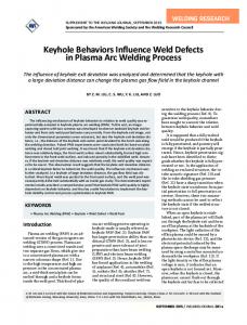
Fig. 1 — Schematic diagram showing the dimensions of the welded specimens used in the tension tests.
phase composition change through solidification temperature range from TiN to (MTi)(CN), where M stands for other metallic elements. The beneficial impact of nitrogen on the carbide morphology in unidirectional and single crystal Ni-based alloys was reported by several investigators (Refs. 14, 17). It has been also revealed that the addition of nitrogen to CMSX-4, a single crystal Ni-based superalloy, increases the number of solidification defects, especially high-angle boundaries (Ref. 18). According to Nage et al. (Ref. 8), nitrogen has a positive effect on decreasing the compositional difference between the dendrites and interdendrites regions in 904L stainless steels. It has been recognized that nitrogen improves the depth of welding penetration, corrosion resistance, and mechanical properties in stainless steels (Refs. 7, 8, 19–22). Unlike iron-based alloys, there is a dearth of information on the microstructural and mechanical behavior of Ni-based weld metals obtained by Ar-N2 shielding gases. Therefore, in the current work, the effect of N2 addition in Ar gas on the FZ microstructure plus mechanical properties of Alloy 263 and Alloy X were investigated.
Experimental Method Materials and Sample Preparation In the present study, solution annealed Alloy 263 and Alloy X sheets of 100 x 70 x 1 mm size were prepared. To
ensure about heat treatment condition, specimens were solutionized at 1150ºC for 2 h followed by water quenching. B The chemical compositions and mechanical properties of the test materials are given in Tables 1A and 1B, respectively. Gas tungsten arc welding was carried out by an experienced specialist welder without filler metal. The shielding gas was argon with a maximum 4 vol-% nitrogen fraction, prepared in a special mixer. To protect the Fig. 2 — Optical images of solution heat treated (1150°C/2 weld root against oxidah) base metal. A — Alloy 263; B — Alloy X showing inter granular and intragranular particles within the matrix. tion, to avoid the influence of oxygen on the nitrogen dissolution in shielding gas composition are listed in the welds and promote structure uniforTable 2. The nitrogen content in the mity during solidification, specimens welds was measured by inert gas fuwere welded on a water-cooled copper sion using a LECO analyzer on the backup bar with dimensions of 25 X 15 X weld metal extracted by drilling. 5 cm. Argon was purged continuously The welding speed was measured by from the bottom as the backing gas. the following: Constant welding parameters include the following: current 20 A; diS = x/t (1) ameter of the 2% thoriated tungsten electrode 1 mm; electrode tip angle 60 deg; arc length 3 mm; and the shieldwhere S is the welding speed (mm/s), x ing gas and backing gas flow rate 8 is the length of weld (x = 100 mm), 1/min and 6 1/min, respectively. The and t denotes welding time (s). heat input rate, welding voltage, and The heat input rate was estimated welding speed as the functions of by the following:
Table 1A — Chemical Compositions (wt%) of Test Materials Alloy
C
Si
Mn
Cr
Co
Mo
Fe
Al
Ti
Cu
W
S
N
Ni
Alloy 263 Alloy X
0.05 0.1
0.25 0.15
0.3 0.75
19.58 22.17
19.1 1.3
5.9 9.02
0.48 18.5
0.2 0.15
2.38 –
0.1 0.3
– 0.6
0.0017 0.0053
0.0062 0.0137
bal bal
54-s WELDING JOURNAL / FEBRUARY 2015, VOL. 94
NABAVI SUPP FEB 2015_Layout 1 1/9/15 3:56 PM Page 55
WELDING RESEARCH H = VI/S
(2)
A
B
C
D
where H, , I, and V stand for the heat input rate (J/mm), arc efficiency coefficient ( = 0.65), current (I = 20 A), and the arc voltage (V), respectively.
Microstructural Characterization To examine microstructural features of the weld metal, optical and scanning electron microscope (SEM) were used. Elemental distribution of the precipitations in welds was determined by energy dispersive X-ray analyzer (EDX) coupled with SEM. For samples preparation, specimens were first machined in needed dimensions. Thereafter, they were mounted and ground with SiC abrasive paper down to 1500 mesh grit. The polishing operation was conducted with 3 and 1 m diamond paste. Alloy 263 samples were etched in a solution with 2 part hydrochloric acid, 2 part nitric acid, 3 parts acetic acid, and four drops of glycerin for 4 to 8 s. A solution with 3 parts HCl, 1 part HNO3, and 2 parts glycerin was used to etch Alloy X sections for 25 to 30 s. The size of the equiaxed dendrites and secondary dendrite arm spacing (SDAS) were determined in the etched FZ sections using Clemex image analysis software.
Mechanical Tests Vickers microhardness was measured using a load of 0.49 N. The tensile behavior of the welds was evaluated for all samples welded with various shielding atmosphere. Figure 1 illustrates the configuration of the tensile specimens made in accordance with the specifications of ASTM E8, Standard Test Methods for Tension Testing of Metallic Materials. Each specimen was inspected by X-ray method prior to mechanical tests.
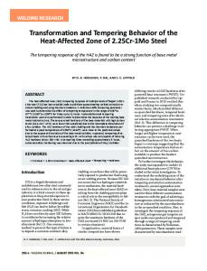
Results and Discussion Base Metals Figure 2A and B show the typical optical microstructure of preweld solution heat treated base Alloy 263 and Alloy X, respectively. As seen from Fig.
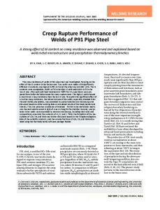
Fig. 3 — SEM microstructure. A — Alloy 263; B — Alloy X weldments; C and D — EDS spec tra from MC and M6C carbides distributed in Alloy 263 and Alloy X matrices, respectively.
Table 1B — Mechanical Properties of Test Materials in the SolutionTreated Condition Material
Yield Strength (MPa)
Alloy 263 Alloy X
424 330
Ultimate Tensile Strength (MPa) Elongation % Hardness (Hv)
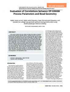
2A and B, both alloys contained dispersed particles in intergranular and intragranular regions of the matrix. Backscattered SEM micrographs of the alloys are shown in Fig. 3A and B. The particles distributed in the matrix of Alloy 263 appear in dark contrast (Fig. 3A) whereas the particles in the grains of Alloy X appear in bright contrast — Fig. 3B. The EDS spectra from the particles, shown in Fig. 3C and D, revealed that they are of the MC-type carbide and M6C-type carbide in Alloy 263 and Alloy X, respectively. Metallographic evidence also elucidated that liquation phenomenon occurred in the HAZ of Alloy X. One of these liquated M6C carbides was shown in bottom left inset of Fig. 3B at higher magnification. This liquated carbide can be compared to a pristine carbide shown in the top right inset of Fig. 3B. What’s more, Fig. 4A shows an optical image of the HAZ in Alloy X. Two liquated M6C can be seen in Fig. 4A. The liquation can be identified by
860 721
56 47
245 240
partial dissolution near the edges of the large carbides. Under the heating conditions experienced in the HAZ, small carbides can totally dissolve in the matrix. In the case of MC carbides, they have been found with two blocky and cylindrical morphologies in the base Alloy 263. For example, one blocky shaped carbide approximately 7 m in size and one cylindrical carbide, 10 m long and about 2 m wide, were shown in Fig. 4B and C, respectively. Several investigators have reported that MC carbide forms generally with cylindrical and blocky morphologies during solidification, hot working process, and aging treatment (Refs. 1, 3). Owing to the large (> 5 m) and medium (1–2 m) average size of the carbides, it is reasonable to assume that the carbides observed in the matrix of Alloy 263 are either primary solidification constituents or secondary phases precipitated during the hot working process. FEBRUARY 2015 / WELDING JOURNAL 55-s
NABAVI SUPP FEB 2015_Layout 1 1/15/15 10:07 AM Page 56
WELDING RESEARCH A
B
Fig. 5 — Nitrogen content in the weld metal as a function of the shielding gas composition.
C
Fig. 4 — Optical images. A — M6C carbides in the HAZ of Al loy X; B and C — MC carbides in base Alloy 263.
Nitrogen Content in the Welds The nitrogen content in the welds as a function of the shielding gas composition was illustrated in Fig. 5. The experimental results demonstrate that the N content of the weld increases with the increasing N2 level in the shielding gas mixture for both alloys. Similar results were found in the previous works on austenitic steels (Refs. 7, 8, 19–22). From Fig. 5, it can be seen that the nitrogen solubility of Alloy X welds is higher than that of Alloy 263 welds. It was found that effective factors on nitrogen solubility in the weld include the alloying element content of the FZ, primary nitrogen level, the surface active element concentration in the weld, and the welding parameters (Ref. 20). Regarding higher primary nitrogen level
in Alloy X, low sulfur concentration for both materials (Table 1A) and higher welding speed for Alloy X Fig. 6 — Influence of shielding gas composition on the size of (Table 2), it is sugequiaxed dendrites d and SDAS λ in welds. gested that the difference in nitrogen solualso shown in Table 2. bility in Alloy 263 and Alloy X may reBased on the experimental results, sult from the presence of various alloywelding speed increases with a nitroing elements. gen rise in the shielding gas. Doping of 4% N2 to Ar leads to increased welding Welding Speed speed by about 20% compared with the pure argon shielded process for Table 2 shows the effect of shieldboth Alloy 263 and Alloy X. The key ing gas composition on welding voltreason is associated with increasing in age. As seen from Table 2, the welding the density of heat flux to anode (samvoltage increases by an N2 rise in Ar. It ple) due to adding N2 to Ar. The heat is consistent with findings by several intensity or heat flux at the anode surresearchers (Refs. 7, 19, 21, 22). The face is given by the following: influence of different shielding gas atmospheres on the welding speed is ∂T Sa = jeϕ wa − k − ε a αT 4 (3) ∂z
Table 2 — Influence of Shielding Gas Composition on the Voltage and Heat Input Rate Shielding Gas Composition
Voltage (V)
Ar Ar1% N2 Ar2% N2 Ar3% N2 Ar4% N2
10.3 10.5 11 11.3 11.4
Welding Speed (mm/s) Alloy 263 Alloy X 1.25 1.3 1.35 1.4 1.5
2 2.05 2.15 2.3 2.4
56-s WELDING JOURNAL / FEBRUARY 2015, VOL. 94
Heat Input Rate (J/mm) Alloy 263 Alloy X 107 ± 1 105 ± 1 105 ± 1 105 ± 1 99 ± 1
67 ± 1 67 ± 1 67 ± 1 63 ± 1 62 ± 1
Equation 3 includes three terms: heating by electron capture, thermal conduction, and blackbody radiative cooling. Here je is current density, ϕwa is work function, k is thermal conductivity, T is the temperature, z is displacement in the direction perpendicular to the anode surface, εa is emis-
NABAVI SUPP FEB 2015_Layout 1 1/9/15 3:56 PM Page 57
WELDING RESEARCH Table 3 —EDS Results of MC Precipitates Observed in Alloy 263 Welds Shielded by Ar and Ar + 4% N2 Gases Elements C Ti Co Cr Mo Ni
A
B
C
D
Shielding Gas (wt%) Pure Ar Ar + 4% N2 10.2 56.4 5.2 8.1 3.2 16.9
13.5 43.7 7.1 9.7 5.1 20.9
sivity of the anode, and finally denotes the Stefan-Boltzmann constant. Some authors take into account an additional term, 5kB/2ejeTp, where kB is the Boltzmann’ constant, and Tp is the plasma temperature at the edge of the sheath. If this term were included, the term proportional to je would increase by about 20%. This would not alter the conclusion of the total heat flux. Another term that has been neglected is the anode fall voltage as well, because the fall can be negative due to strong electron diffusion to the anode, and its impact is in any case small compared with the electron capture term. According to Murphy et al. (Refs. 23, 24), nitrogen addition to argon causes a higher increase in current density and less increase in thermal conductivity of arc, so the total heat flux increases, indicating arc constricts.
Fig. 7 — Influence of nitrogen addition to argon gas on weld metal structure. A — Pure Ar and B — Ar4% N2 for Alloy 263; C — pure Ar and D — Ar4% N2 for Alloy X.
A
B
C
D
Microstructural Investigation Based on the microstructural examination, the FZ of Alloy 263 and Alloy X superalloys consisted of equiaxed dendrites at the center and columnar dendrites around them. The effect of shielding gas composition on the size of the equiaxed dendrites and the SDAS is shown in Fig. 6. Experimental results show that increasing the N content in the weld metal leads to reduction of the equiaxed grains size and the SDAS in both alloys. According to Fig. 6, the size of the equiaxed dendrites decreases over 11% in Alloy 263 welds and 27% in Alloy X welds by addition of 4 vol-% nitrogen in the shielding gas in comparison with the pure argon shielded method. In addition, the SDAS in Alloy 263 welds reduced from 16 ± 1 m for pure argon to 11 ± 1 m for Ar-4% N2 shielding gas. A similar decline in the SDAS occurred in Alloy X weld metals (Fig. 6).
Fig. 8 — Influence of shielding gas composition on the microstructure of Alloy 263 welds. A — Pure Ar; B — Ar2% N2 ; C — Ar3% N2; D — Ar4% N2 .
Figure 7A–D displays the columnar zone of the weld metal of Alloy 263 and Alloy X specimens obtained by pure Ar and Ar-4% N2 shielding gases. Comparing Fig. 7A–D indicates that the weld structure has been altered due to the welding by N2-containing shielding gas. It is known that the SDAS depends on the cooling rate and mobility factor. In
Ni-base alloys, the SDAS correlates with the cooling rate by the following: ~ (tf)1/3 ~ ()–1/3 ~ (G)–1/3
(4)
where tf is the solidification time, is the cooling rate, G is the temperature gradient, and is the solidification rate (Refs. 6, 25). According to EquaFEBRUARY 2015 / WELDING JOURNAL 57-s
NABAVI SUPP FEB 2015_Layout 1 1/9/15 3:56 PM Page 58
WELDING RESEARCH A
B
C
D
Fig. 10 — SEM image of Alloy 263 weld met al prepared with Ar4% N2 shielding gas.
Fig. 9 — Optical images of Alloy 263 specimens welded by different shielding gas composi tions. A and B — Pure Ar; C — Ar3% N2; D — Ar4% N2. (Arrows show MCtype carbides.)
tion 4, the cooling rate is the product of the temperature gradient and solidification rate. Since the sample geometrical shape and environmental condition are the same for all tests, the temperature gradient and subsequently the cooling rate are constant. It was found that the mobility factor is a function of surface tension and partition coefficient (Ref. 8). Therefore, the reduction in the SDAS is attributed to the change in surface tension and chemical composition due to the nitrogen rise in the weld metal. It is necessary to mention that the decrease in the SDAS corresponds with a more homogeneous distribution of alloying elements (Ref. 25). Figure 8A–D illustrates typical optical micrographs associated with the effect of the nitrogen amount in the shielding gas on the weld metal microstructure adjacent to the HAZ in Alloy 263. As seen from Fig. 8A–D, dendritic structure of the welds is significantly changed by increasing in the nitrogen content. As a case in point, it is clear that the area of columnar zone is considerably decreased by a nitrogen rise in the shielding gas. That is, the ratio of the columnar area to the FZ area decreased from 0.55 for specimens welded with Ar to less than 0.2
for weldments prepared with Ar-4% N2 shielding gas; nitrogen addition leads to a noticeable extending in the equiaxed zone in the weld metal. Optical micrographs of the Alloy 263 weld metals obtained by different shielding gas compositions are depicted in Fig. 9A–D. Two precipitates with blocky and cylindrical morphologies are evident in Fig. 9A and B, respectively. Table 3 represents the EDS results of the precipitates in Alloy 263 FZ welded with N2 free and 4% N2 containing shielding gases. According to Table 3, the observed precipitates in the Arshielded weld are MC-type carbide due to the presence of C and Ti, which contain other elements. High amounts of nickel, chromium, and cobalt detected definitely indicates high interference with the matrix surrounding the precipitate. Similarity of blocky and cylindrical phases in Fig. 4B and C, and Fig. 9A and B also supports the existence of MCtype carbides in the weld metal. Based on the metallographic investigation, it was found that with increasing the nitrogen content in the weld metal, the number of medium size precipitates (1–2 m) increases in the Alloy 263 FZ. The quantity of these precipitates in the weld made by Ar-4% N2 shielding gas exceeded four times as
58-s WELDING JOURNAL / FEBRUARY 2015, VOL. 94
much as the number of them in the weld made by pure Ar. The orange-like color of these secondary phases suggests that they are either nitride compositions or carbides similar to Fig. 9A and B detected in the specimens welded with pure argon. In order to identify these precipitates, SEM images of the different N-bearing welds were studied. Figure 10 illustrates an SEM image of the weld metal prepared with Ar-4% N2 shielding gas. EDS analysis related to one of these precipitates was listed in Table 3. The analysis result reveals high C concentration. However, nitrogen was not detected in any of the analyzed precipitations; it doesn’t suggest the absence of nitrogen because the precision limit of this analysis was 0.1 wt-%. Low atomic weight of C and N elements makes it difficult to identify them in the EDS analysis, though the high wt-% of C supports the presence of carbide or carbo-nitride enriched in Ti and Cr. It should be noted that beside large and medium size precipitates, some very small phases were also observed. It is likely that they are of either M23C6-type carbides precipitated along the welds grain boundary or MN-type nitrides like TiN particles formed in the weld pool. Ramirez et al. (Ref. 16) identified both nanoscale M23C6 carbides precipitated along grain boundary and very small nitrides (< 50 nm) in strain-to-fracture Ni-based sample strained 1.6% at 956ºC for 10 s. Of course, it is necessary to consider that we did not apply any heat treatment on the weldments.
NABAVI SUPP FEB 2015_Layout 1 1/9/15 3:56 PM Page 59
WELDING RESEARCH A
C
B
D
Fig. 11 — Influence of shielding gas composition on the microstructure of Alloy X welds. A — Pure Ar; B — Ar2% N2 ; C — Ar3% N2 ; D — Ar4% N2.
Nonetheless, regarding the presence of Ti, a strong nitride former, and high amounts of nitrogen in the melt, it is possible to precipitate nanoscale TiN particles throughout the liquid metal during solidification. Therefore, it is suggested that the heterogeneous nucleation of carbides on extremely fine TiN precipitates is the reason for the increasing in number of MC precipitates resulted from the nitrogen rise in Alloy 263 welds. The impact of TiN precipitates on motivating heterogeneous nucleation of carbides at a higher temperature reported before (Ref. 14). It has been previously ascertained in GTA welds of Alloy 690 using thermodynamic calculations that TiN is formed in higher temperatures in the melt and is changed to the TiC phase (TiN isomorph phase) during solidification in the weld metal (Refs. 16, 17). Hence, this phase transformation is likely to be the cause for nonidentification of TiN particles in none of the specimens welded with N2 containing shielding gas. On the other hand, investigation of optical micrographs of Alloy X welds obtained by different shielding gases showed that the area of the equiaxed grains has not been changed with increasing N2 content in Ar. Figure 11A–D
shows the weld metal microstructure of Alloy X adjacent to the HAZ resulted from different shielding gas composition. As seen from Fig. 11A–D, no change was observed in the area of the columnar region of the welds with an addition of nitrogen to argon. Based on the above discussions, this difference between Alloy 263 and Alloy X welds can be described by the role of TiN or carbonitrides formed in Alloy 263 welds. Reasons confirming the aforementioned notion include an absence of Ti in Alloy X (Table 1A); the presence of N in Alloy X welds about twice as much as Alloy 263 weld metals made by similar shielding gases (Fig. 5); and a high affinity between Ti and N, plus no alteration in the area of equiaxed grains in the Alloy X welds. Moreover, it should be stated that no precipitation was observed in Alloy X welds prepared with all of the shielding gases. As a result, the main reason for significant grain refinement of Alloy 263 weld metal resulted from 4% N2 added to Ar gas is based on the idea that the dendrite nucleation was intensified heterogeneously on MC, (MTi)(CN), or TiN precipitates. Black arrows in Fig. 9C and D show three MC carbides nuclei at the center of
Fig. 12 — Effect of nitrogen content in ar gon gas on the ultimate tensile strength of weldments.
Fig. 13 — Vickers hardness of the weld metal as a function of the shielding gas composition.
three equiaxed grains. The investigation of the optical images shows that the number of cylindrical carbides decreases as the nitrogen content in the weld increases. That is, increasing the nitrogen content of the weld leads the cylindrical carbides to become blocky. This finding is in good agreement with all investigators (Refs. 14, 17). A clear mechanism for this change in morphology has not yet been found. In addition, with increasing nitrogen content in the weld pool, the quantity of large size carbides significantly decreased.
Mechanical Tests Results The effect of nitrogen content on the ultimate tensile strength (UTS) is shown in Fig. 12. Based on the experimental results, UTS increases with augmenting the amount of nitrogen in argon gas. The main reason is related to the microstructure refinement discussed in the previous section. The second reason is precipitation strengthening caused by raising the number of MC carbides in the Alloy 263 weld zone. Indeed, glide of dislo-
FEBRUARY 2015 / WELDING JOURNAL 59-s
NABAVI SUPP FEB 2015_Layout 1 1/9/15 3:56 PM Page 60
WELDING RESEARCH cations could be hindered by MC precipitates, so the dislocations pile-up at these obstacles. Hence, more stress is needed to move the dislocations. Figure 13 displays the microhardness of the weld as a function of the shielding gas composition. Microhardness measurements on the as-welded specimens indicate that the hardness of the weld is less than that of the base metal for both alloys (Table 1B and Fig. 13). It is interesting to note that Vickers hardness reached HV 238 and HV 227, respectively, for Alloy 263 and Alloy X welds resulting from 4% N2 addition to Ar. This finding was consistent with microstructural observations; in other words, the refinement of the dendritic structure (Figs. 7, 8) and interstitial solid solution strengthening and precipitation hardening (Fig. 9) have been obviously identified as hardening mechanisms in the weld zone.
Conclusions The weld metal microstructures and mechanical properties due to welding by different Ar-N2 shielding gases were examined in Alloy 263 and Alloy X. The results are summarized as follows: 1) In both alloys, with increasing the amount of N2 in Ar gas, the N level in the welds increased and dendritic structures were refined. 2) A considerable decrease in the columnar region in Alloy 263 was observed due to an addition of 4% N2 in Ar, while such a similar event did not occur in Alloy X. 3) As the N content of the Alloy 263 weld metal increases, the number of MC precipitates increases, and they tend to precipitate in blocky form. 4) It is suggested that heterogeneously promoted nucleation of the dendrites and MC carbides during solidification are the main reasons for the microstructural modification in Alloy 263 weld. 5) The UTS increased from 773 MPa and 665 MPa for Ar gas to 815 MPa and 715 MPa for Ar-4% N2 shielding gas in Alloy 263 and Alloy X weldments, respectively. 6) The hardness of the weld augmented with increasing the N content of the weld zone in both superalloys.
Acknowledgments
The authors would like to acknowledge the MAPNA Group for financial support of this research and employees of MavadKaran Co., especially Mohammad Cheraghzadeh and Amin Amjadi, for supplying materials and kind assistance. References 1. Wang, W. Z., Hong, H. U., Kim, I. S., Choi, B. G., Jeong, H. W., Kim, M. Y., and Jo, C. Y. 2009. Influence of ' and grain boundary carbide on tensile fracture behaviors of Nimonic 263. Materials Science and Engineering A 523: 242–245. 2. Zhao, J. C., Larsen, M., and Ravikumar, V. 2000. Phase precipitation and timetemperature-transformation diagram of Hastelloy X. Material Science & Engineering: 112–119. 3. Zhao, J. C., Ravikumar, V., and Beltran, A. M. 2001. Phase precipitation and phase stability in Nimonic 263. Metallurgical and Materials Transactions A 32A: 1271–1282. 4. Hong, H .U., Kim, I. S., Choi, B. G., Jeong, H. W., and Jo, C. Y. 2008. Effects of temperature and strain range on fatigue cracking behavior in Hastelloy X. Materials Letters 62: 4351–4353. 5. DuPont, J. N., Lippold, J. C., and Kiser, S. D. 2009. Welding metallurgy and weldability of nickel-base alloys. John Wiley and Sons Co., New Jersey. 6. Kou, S. 2003. Welding Metallurgy. 2nd Ed., John Wiley and Sons Co., New Jersey. 7. Shankar, V., Gill, T. P. S., Mannana, S. L., and Sundaresan, S. 2003. Effect of nitrogen addition on microstructure and fusion zone cracking in Type 316L stainless steel weld metals. Materials Science and Engineering A 343: 170–181. 8. Nage, D. D., Raja, V. S., and Raman, R. 2006. Effect of nitrogen addition on the microstructure and mechanical behavior of 317L and 904L austenitic stainless steel welds. Journal of Material Science 41: 2097– 2112. 9. Iorio, L., Cortie, M., and Jones, R. 1994. Technical note: solubility of nitrogen in experimental low-nickel austenitic stainless steels. Journal of the South Africa Institute of Mining and Metallurgy: 173–177. 10. Christ, H. J., Chang, S. Y., and Krupp, U. 2003. Thermodynamic characteristics and numerical modeling of internal nitridation of nickel base alloys. Materials and Corrosion 54(11): 887–894. 11. Penna, C. D. 2000. Development of new nitrided nickel-base alloys for high temperature applications. The Minerals, Metals &
60-s WELDING JOURNAL / FEBRUARY 2015, VOL. 94
Materials Society: 821–828. 12. Abdulrahman, R .F., and Hendry, A. 2001. Solubility of nitrogen in liquid nickelbased alloys. Metallurgical and Materials Transactions B 32B: 1103–1112. 13. Kowanda, C., and Speidel, M. O. 2003. Solubility of nitrogen in liquid nickel and binary Ni–Xi alloys (Xi ¼ Cr, Mo, W, Mn, Fe, Co) under elevated pressure. Scripta Materialia 48: 1073–1078. 14. Cutler, E. R., Wasson, A. J., and Fuchs, G. E. 2008. Effect of minor alloying additions on the carbide morphology in a single crystal Ni-base superalloy. Scripta Materialia 58: 146–149. 15. Ramirez, A. J., and Lippold, J. C. 2004. High temperature behavior of Ni-base weld metal Part II. Insight into the mechanism for ductility dip cracking. Materials Science and Engineering A 380: 245–258. 16. Ramirez, A. J., and Lippold, J. C. 2004. High temperature behavior of Ni-base weld metal Part I. Ductility and microstructural characterization. Materials Science and Engineering A 380: 259–271. 17. Huang, X., Zhang, Y., Liu, Y., and Hu, Z. 1997. Effect of small amount of nitrogen on carbide characteristics in unidirectional Ni-base superalloy. Metallurgical and Materials Transaction A 28A: 2143–2147. 18. Cutler, E. R., Wasson, A. J., and Fuchs, G. E. 2009. Effect of minor alloying additions on the solidification of single-crystal Ni-base superalloys. Journal of Crystal Growth 311: 3753–3760. 19. Huang, H. 2009. Effects of shielding gas composition and activating flux on GTAW weldments. Materials and Design 30: 2404–2409. 20. Toit, M. 2001. The behavior of nitrogen during the autogenous arc welding of stainless steel. PhD thesis, University of Pretoria, Pretoria. 21. Lin, Y. C., and Chen, P. Y. 2001. Effect of nitrogen content and retained ferrite on the residual stress in austenitic stainless steel weldments. Materials Science and Engineering A 307: 165–171. 22. Tseng, K. H., and Chou, C. P. 2003. The study of nitrogen in argon gas on the angular distortion of austenitic stainless steel weldments. J. Mater. Process Technology 142: 139–44. 23. Murphy, A. B., Tanaka, M., Tashiro, S., Sato, T., and Lowke, J. J. 2009. A computational investigation of the effectiveness of different shielding gas mixtures for arc welding. Applied Physics 42: 115205 (14 pp). 24. Murphy, A. B., Tanaka, M., Yamamoto, K., Tashiro, S., Sato, T., and Lowke, J. J. 2009. Modelling of thermal plasmas for arc welding: the role of the shielding gas properties and of metal vapour. Applied Physics 42: 194006 (20 pp). 25. Franke, M. M., Hilbinger, R. M., Konrad, C. H., Glatzel, U., and Singer, R. F. 2011. Numerical determination of secondary dendrite arm spacing for IN738LC investment castings. Metallurgical and Materials Transactions A 42A: 1847–1853.