Sarafan Supplement June 2012_Layout 1 5/10/12 1:33 PM Page 182
Effects of Welding Direction and Position on Susceptibility to Weld Metal Transverse Cracking in Welding High-Strength Pipeline Steel with Cellulosic Electrodes Welding position and welding direction can contribute interactively in terms of the provision of the conditions for hydrogen cold cracking in weld metal
BY S. SARAFAN, F. MALEK GHAINI, AND E. RAHIMI
ABSTRACT
WELDING RESEARCH
The higher tendency for weld metal transverse cracking at certain positions as observed in field welding of highstrength pipeline steels was investigated under laboratory conditions. Experimental results confirmed reproducibility of such behavior and significance of a number of variables. It is shown that welding position and welding direction can contribute interactively in terms of the provision of the conditions for hydrogen cold cracking in the weld metal. A higher level of hydrogen absorption in the overhead position and an inward weld direction are proposed to be the metallurgical factors involved in an increase in cracking susceptibility at the six o’clock position in pipeline girth welds.
Introduction Transverse weld metal cracking is known as a potential defect in field welding of high-strength steel transmission pipelines especially when using the shielded metal arc welding (SMAW) process with cellulosic electrodes. This type of cracking is known to be related to the weld metal hydrogen content and can occur hours after completion of welding (Refs. 1–5). Although no standard procedure exists for the assessment of susceptibility of transverse cracking in pipeline welding, M. Fiedler et al. have proposed guidelines for such assessment based on S. SARAFAN and F. M. ALEK GHAINI (
[email protected]) are with Dept. of Materials Engineering, Tarbiat Modares University, Tehran, Iran. E. RAHIMI is with AMA Industry Co., Tehran, Iran.
182-s JUNE 2012, VOL. 91
bend testing and investigated the effects of preheat and weld metal strength (Ref. 6). On the other hand, field experience has shown that cracking occurs more in the six o’clock position of pipeline girth welds (Refs. 7, 8). This defect needs to be treated seriously, especially as sometimes it could not be detected through common radiographic inspection methods (Ref. 8). A review of the literature shows that in spite of much research being performed on the subject of the assessment of hydrogen cold cracking susceptibility, either in the heat-affected zone (HAZ) or the weld metal (Refs. 9, 10), the problem of higher susceptibility of cracking as related to welding direction and welding position has not gained much attention. The aim of the present research is to establish whether factors other than preheat and weld metal strength can play a significant role in the tendency for transverse weld metal cracking and whether such behavior can be reproduced under laboratory conditions. The result can be expected to have an important impact on the selection of preventive measures with respect to avoidance of hydrogen cracking in welding of high-strength steels especially in field welding of transmission pipeline construction projects.
Experimental Procedure The chemical composition of the base
KEYWORDS Shielded Metal Arc Welding SMAW Weld Metal Transverse Cracking Hydrogen Cracking Welding Position Welding Direction
material is given in Table 1. It was a 20mm-thick steel plate obtained from a pipe mill, which used the same base material for production of 56-in. OD API 5L X 70 pipes. The plates were cut into 300-mmlong by 125-mm-wide pieces to be able to place them in the fixture. The plates were welded to each other by the SMAW method. Consumable materials used in different passes were as follows: • AWS E6010, 4 mm diameter for root pass. • AWS E8010-P1, 4 mm diameter for hot and filling passes. • AWS E8010-P1, 5 mm diameter for cap passes. The welding process was conducted with the voltage in the range of 23–24 V and the current in the range of 120–160 A. A fixture was designed to weld pipeline materials in the form of plate segments in various positions — Figs. 1, 2. The fixture was made of 80-mm-thick steel plates with six removable clamps incorporated. After fixing the test coupon plates into the fixture, welding was performed. The welds were made with various preheats including that recommended by previous researchers (Ref. 6) and with no preheat. For other welding parameters such as voltage, current, and travel speed, the actual field welding conditions for an actual 56in. transmission pipeline with the same thickness but for various positions around the girth weld were used. Experiments were designed mainly to investigate the effects of two specific parameters: welding position and direction. The combinations of welding parameters tested are shown in Table 2. Trial number 3 was arranged parallel to trial number 1 with preheat in order to check if the test setup was sensitive enough to the known parameter of preheating. Weld directions similar to that of actual field girth welding were considered, i.e., in overhead position
Sarafan Supplement June 2012_Layout 1 5/11/12 2:33 PM Page 183
Table 1 — Chemical Composition of Base Metal (wt-%) C Mn Si Cr Ni Nb
0.08 1.6 0.15 trace 0.15 0.044
Ti P S V Cu Mo
0.018 trace trace 0.04 0.004 0.2
A
Electrodes
B
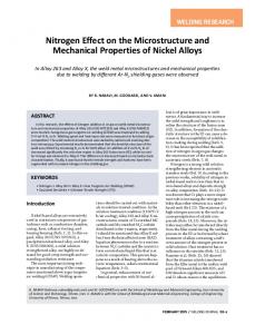
Fig. 1 — Fixture with six removable clamps and the plate in place.
A
B
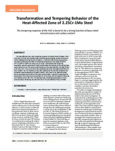
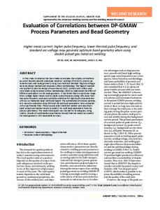
Fig. 3 — Two different directions of welding: A — From the edges of the plate inward: B — from the plate center outward.
Fig. 4 — Dimensions of bend test specimen. Width = 10 mm, length = 300 mm, thickness = 20 mm.
along with the metallographic studies. The diffusible hydrogen was measured by the mercury method based on AWS A4.3 (Ref. 12). This method and apparatus are mainly designed for measuring diffusible hydrogen for basic low-hydrogen electrodes, and in this sense the capacity of the container for the volume of hydrogen was 60 mL. Based on Yurioka et al. (Ref. 3) for cellulosic electrodes, if the specimen for testing diffusible hydrogen is immediately quenched after welding, the amount of diffusible hydrogen could be around 60 mL/100g. However, when the specimen after welding was given 10 min to allow some hydrogen to escape before quenching, the amount of diffusible hydrogen was brought down to 15 mL/100g. Thus, it was decided this delay time before quenching would be a good solution to enable using the available equipment for
comparison purposes between various welding conditions of cellulosic electrodes. It must be mentioned that the result obtained with this 10-min delay cannot and should not be compared with those obtained with the normal procedure. The welding consumable for hydrogen measurement was the E8010-P1 type with diameter 5 mm, which according to the welding procedure was used for fill and cap weld layers.
Table 2 — Results of Weld Tests on API X70 Pipe Plate Welding position Trial Number Welding progression Preheat temperature (°C) Interpass temperature (°C) Heat input (kj/mm-1) Cracks observed in RT Cracks observed in bend test
Overhead 1
2
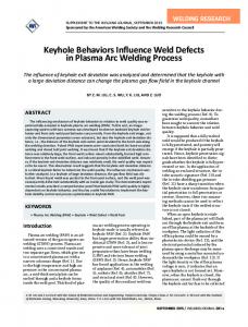
Fig. 2 — Two different positions of welding: A — Overhead position; B — flat position.
Flat 3
4
5
6
→←
←→
→←
←→
→←
→←
20 40 3.3 0 25
20 40 4 0 4
130 140 3.2 0 3
20 40 4.7 0 1
20 40 5.1 0 15
20 40 3.3 0 22
Results and Discussion No crack was identified in radiographic examination of any of the welds tested, but cracks were observed in a number of bend tests. Metallographic examination of the corresponding samples taken in the aswelded condition (i.e., no bending) also revealed transverse weld metal cracks with similar relative severity confirming the validity of the bend test — Fig. 6A. Both in the bend test and metallographic examinations, cracks if present were located in the upper part of the thickness (i.e., in the fill passes just before the cap pass). The crack lengths ranged from 0.5 to 5 mm. From Table 2, it appeared that with the application of preheat, as would have been expected, the number of cracks identified in the bend tests were reduced significantly and almost eliminated. On the WELDING JOURNAL 183-s
WELDING RESEARCH
welding from the edges of plate inward and in flat position welding from the plate center outward. Figure 3 illustrates the two directions schematically. After completion of welding, the test plates were kept in the fixture for 24 h to allow any potential delayed hydrogen cracking process to take effect. Then a radiographic test was performed according to API 1104 (Ref. 11) to check if any cracks could be identified. However, because hydrogen cracks can be so minute that they may not be identified through radiography, the weld specimens were subjected to bend testing. On the other hand, it is known that fisheyes can occur in bend tests in the presence of diffusible hydrogen in carbon steel (Ref. 1). Thus, a dehydrogenization treatment was performed for 16 h at 250°C in the furnace in order to eliminate the possibility of formation of fisheye defects during bend testing and to avoid mistaking them for hydrogen cracks. From each test run, two longitudinal specimens were taken out by machining. One specimen was subjected to bend testing; the other was subjected to metallographic examination. The bend test conditions and dimension of the mandrel were similar to those used by a previous researcher due to the similarity (Ref. 6) in the objectives of the test. In this bend test, a 180mm mandrel was used. The bend test specimen consisted partly of weld metal and is shown in Fig. 4. The setup for bending of specimens with a 180-mm-diameter mandrel is shown in Fig. 5. For metallographic examination, the specimens were machined and ground in two different directions: from top and side faces of the specimens. Thus, the mirror of the face of the weld metal, which was under tension in bend testing, was also subjected to metallographic examination. The hardness survey tests were performed
Sarafan Supplement June 2012_Layout 1 5/11/12 2:34 PM Page 184
A
Fig. 5 — Three-point bend test with 180-mm-diameter mandrel.
B
WELDING RESEARCH
other hand, the number of cracks observed in the bend tests were significantly affected by variations in the welding parameters. Considering the results presented in Table 2, welding in the overhead position and an inward welding direction both have had an important impact on increasing the cracking tendency. Weld metal diffusible hydrogen content measurement tests were performed in the flat and overhead positions. The results as shown in Table 3 indicate that a higher level of hydrogen was absorbed in the overhead position. The average diffusible hydrogen in the weld metal made with E8010-P1 type electrode in the overhead position with a 10-min delay before quenching came up as 42 mL/100g in comparison with 19 mL/100g in the flat position. The above figures as shown in Table 3 were obtained by averaging out the results of four measurements. The table also shows the calculated standard deviations. Statistical analysis of the result of hydrogen measurements can be made by using t distribution test (Ref. 13). Analysis shows that with a 90% confidence limit the estimate for diffusible hydrogen content with 10 min delay time in the overhead position is 42 ± 13 mL/100g but that in the flat position is 19±3.3 mL/100g. The above analysis indicates that the difference between the diffusible hydrogen content is significantly affected by the weld position. However, considering the complexity of the test procedure, and the fact there was not
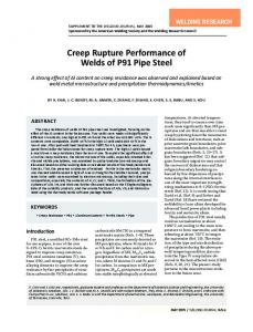
Fig. 6 — Examination of cracks in specimen with inward progression and overhead weld position in the following: A — 20x metallographic specimen that does not bend through the thickness and from side view; B — bent specimen. The appearance of cracks in both examinations is transverse with 45 deg.
much track record available in the factory on hydrogen absorption in the weld metals of cellulosic electrodes used, it is too early to quantify the effect of weld position on hydrogen for a cellulosic electrode. From Table 2, it is apparent the heat input in the overhead position was lower on average compared to that in the flat position. With the lower heat input, a higher cooling rate is experienced. Therefore, it can be proposed that welding in the overhead position can result in an increase in the susceptibility to cold cracking by providing a higher cooling rate that, in turn, may result in a higher level of diffusible hydrogen remaining in the weld metal after the completion of welding. However, by increasing the cooling rate, a harder microstructure can be formed in carbon manganese weld metal
and, at the same time, the escape of diffusible hydrogen can be slowed down. Hardness measurements indicate some correlation between hardness and weld position (i.e., welding heat input). The maximum, average, and minimum hardness of the weld metal in the fill passes measured in more than ten locations of a weld made in the overhead position was 205, 179, and 138 HV, respectively, in comparison with 201, 175, and 110 HV for a weld made in the flat position. As can be seen, considering the variations and uncertainties usually involved in hardness measurements and the weld microstructures, it is only the minimum hardness in the flat position that can be interpreted as lower. So far, the effect of the welding position has been discussed, so now the question must be addressed of how weld direction can affect weld metal transverse cracking. It is a known fact that hydrogen cracking is not only affected by the amount of weld metal diffusible hydrogen and the microstructure, but also by the magnitude of residual stresses. The most important hypothesis that was arrived at and is now put forward is that welding direction can affect the state of weld residual stresses and that, in turn, can affect the tendency toward hydrogen cracking. Inward welding directions along with an overhead welding position occur together when field welding at the 6 o’clock location of transmission pipelines with the SMAW process using cellulosic electrodes. So, in continuation, the researchers are pursuing the means to test the relation of weld direction and weld residual stresses. This will include calculation of weld residual stresses by simulation and numerical methods supported by direct measurements of residual stresses by destructive and nondestructive techniques.
Conclusions • The higher tendency for transverse cracking of the weld metal in the 6 o’clock position in field welding of highstrength transmission pipelines with the SMAW process using cellulosic
Table 3 — Results of Diffusible Hydrogen Measurements Electrode Type Trial No. Welding Position Delay Time (s) Specimens Diffusible Hydrogen (mL/ 100g) Standard Deviation T test distribution by confidence limit of 90%
184-s JUNE 2012, VOL. 91
E 8010-p1 1 Flat 600
2 Overhead 600
1
2
3
16.2
22.4
20.3 2.86 19±3.3
4 17.1
1
2
36.5
58.5
3 31.5 11.73 42±13.5
4 41.4
Sarafan Supplement June 2012_Layout 1 5/10/12 2:30 PM Page 185
References 1. Bailey, N., and Coe, F. R. 1973. Welding steels without hydrogen cracking. Abington Publishing and ASM International pp. 5–7. 2. Lancaster, J. F. 1999. Metallurgy of Welding. 6th edition, Abington Publishing. 3. Yurioka, N., and McDonald, J. 1999. Weld metal hydrogen cracking in pipeline girth welds. First International Conference on Weld Metal Hydrogen Cracking in Pipeline Girth Welds, Wollongong, Australia. 4. Sawhill, J. M., Dix, A. W., Savage W. F. 1974. Modified implant test for studying delayed cracking. Welding Journal 53(12): 554-s to 560-s.
5. Borland, J. C. 1960. Cracking tests for assessing weldability. British Welding Journal. October, pp. 623–637. 6. Fiedler, M., Fischer, J., Posch, G., and Berger, W. 2006. Investigation of HAC-susceptibility of multilayer welds with the “bead bend test” procedure and examples. Bohler Welding Austria GmbH, Kapfenberg, Austria. 7. ESAB Welding Handbook, Consumables for manual and automatic welding, 8th edition. 8. Malek, F., Roshani, M. A., Akhavan, M., and Gholizade, S. 2008. Detectability of transverse cracks in gas and oil pipeline girth welds. 2nd International Conference on Technical Inspection and NDT. Tehran, Iran. 9. Sarafan, S., Malek, F., and Rahimi, E. 2010. Weld metal hydrogen cracking in pipeline constructions. International Pipeline Conference (IPC), Calgary, Canada. 10. Pitrun, M. 2004. The effect of welding parameters on levels of diffusible hydrogen in weld metal deposited using gas shielded rutile flux cored wires. University of Wollongong, Wollongong, Australia. 11. ANSI/API 1104, Welding Pipelines and Related Facilities, 19th edition. Washington, D.C.: American Petroleum Institute. 12. AWS A4.3-93, Standard Methods for Determination of Hydrogen Content of Martensitic, Bainitic, and Ferritic Steel Weld Metal Produced by Arc Welding. 1993. Miami, Fla.: American Welding Society. 13. Triola, M. F., and Guardino, K. 1997. Elementary Statistics, 7th edition, Addison Wesley Longman.
Submit a New Products Item for Consideration If your company has a new welding, fabricating, or manufacturing product readily available, the details required to be considered for possible publication in the Welding Journal’s Product & Print Spotlight section are as follows: • Press release with the product’s name, important features, and specific industries it’s aimed for • High-resolution jpg or tiff photo (266 or more dpi). Please e-mail submissions to Associate Editor Kristin Campbell at
[email protected].
CAN WE TALK? The Welding Journal staff encourages an exchange of ideas with you, our readers. If you’d like to ask a question, share an idea or voice an opinion, you can call, write, e-mail or fax. Staff e-mail addresses are listed below, along with a guide to help you interact with the right person. Publisher Andrew Cullison
[email protected], Extension 249 Article Submissions
Managing Editor Zaida Chavez
[email protected], Extension 265 Design and Production
Editor Mary Ruth Johnsen
[email protected], Extension 238 Feature Articles
Senior Production Coordinator Brenda Flores
[email protected], Extension 330 Production
Associate Editor Howard Woodward
[email protected], Extension 244 Society News, Personnel
Advertising Sales Director Rob Saltzstein
[email protected], Extension 243 Advertising Sales
Associate Editor Kristin Campbell
[email protected], Extension 257 New Products News of the Industry
Advertising Sales & Promotion Coordinator Lea Paneca
[email protected], Extension 220 Production and Promotion
Advertising Production Manager Frank Wilson
[email protected], Extension 465 Advertising Production Peer Review Coordinator Melissa Gomez
[email protected], Extension 475 Peer Review of Research Papers
Welding Journal Dept. 550 N.W. LeJeune Rd. Miami, FL 33126 (800) 443-9353 FAX (305) 443-7404
WELDING JOURNAL 185-s
WELDING RESEARCH
electrodes is reproducible under laboratory conditions by separately testing the effects of welding position and welding direction. • The number of cracks revealed after bending the specimens increases both when welding in the overhead position and when welding with inward weld runs. • The increased cracking tendency observed at the 6 o’clock position is the combined effect of the welding direction and the welding position. • The diffusible hydrogen content of the weld metal made with a cellulosic electrode in the overhead position is more than that in the flat position.