and analyses of the thin films by ellipsometry, surface profilometry and transmission ...... material sticks to the substrate and not to its own particles. PVD can be ...
WET ETCHING OF OPTICAL THIN FILMS
Curt Edström
THESIS WORK 2010 CHEMICAL ENGINEERING
WET ETCHING OF OPTICAL THIN FILMS
Curt Edström
This thesis work is performed at Jönköping Institute of Technology within the subject area Chemistry. The author is responsible for the given opinions, conclusions and results. Supervisors: Peter Leisner and Maarten Rymenans Examiner: Bo Nordström Credit points: 30 hp Date: 101203
Postal Address: Box 1026 551 11 Jönköping
Visiting Address: Gjuterigatan 5
Telephone: 036-10 10 00
Abstract
Abstract Evaluation of the wet etching properties of several different thin film oxides grown by physical vapour deposition was performed in this work. MgO, Al2O3, SiO2, TiO2, HfO2 ZrO2 and Y2O3 were coated on two types of substrates; Si and borosilicate glass and etching tests were performed in different etching solutions. MgF2 thin films have also been evaluated. Important aspects of the choice of the thin films was taken into account in order to match to good optical properties such as refractive index (n), extinction coefficient (k) and optical thickness (TP) as well as good chemical properties in the wet etching process. A description is made of the physics of optical filters and how a combination of different oxides stacked onto each other can create interference filters. A description of the manufacturing process of the thin films where physical vapour deposition (PVD) was used is presented. Thermal shift of the optical spectra caused by porous coatings was investigated and analyses of the thin films by ellipsometry, surface profilometry and transmission spectrophotometry have been performed. The wet etching properties were evaluated by monitoring the transmission insitu on transparent borosilicate glass substrates. A method of how to measure the wet etching rate for different thin films is described. A computer software was used to calculate the Pourbaix diagrams in order to understand the chemical behaviour of the etching solutions. The pH can have a significant impact on the etching behaviour. In case of TiO2, it can be dissolved in an alkaline solution of H2O2. The catalytically process behind this is evaluated. Etching rate for both Y2O3 and SiO2 were matched by adjusting the etchant concentration as a case example. The group IVB oxides are difficult to etch. The catalytic etching of TiO2 with peroxide is slow but detectable. Al2O3, Y2O3 and MgO are reasonably easy to etch but have too low refractive indices to be useful in multilayer optical filters. The In-situ etching instrument was found to be very useful for measuring etching rates.
1
Summary
Sammanfattning Utvärdering av våtkemiska egenskaper för flera olika oxidtunnfilmer utfördes i detta arbete på tunnfilmer av MgO, Al2O3, SiO2, TiO2, HfO2 ZrO2 and Y2O3 vakuumdeponerade på både kiselwafers och borosilikatglas. Etstester gjordes med ett flertal etslösningar. Även MgF2-tunnfilmer utvärderades . Både optiska och kemiska egenskaper togs i beaktande vid utvärderingen av tunnfilmerna. De optiska lagar som gäller för tunnfilmer redovisas, bl a hur kombinationer av olika oxider kan skapa interferrensfilter. En beskrivning av tillverkningsprocessen varvid PVD användes presenteras. Termiskt skift av det optiska transmissionsspektrat orsakat av porositet undersöktes. Analyser av tunnfilmerna med ellipsometri, profilometri och transmissions spektroskopi utfördes. Våtetsningsegenskaperna utvärderades genom att mäta in-situ vid etsprocessen på transparenta borosilikatglassubstrat. Metoden för att mäta etshastigheten för olika oxider är beskriven. Datorberäkningar av pourbaixdiagram användes för att skapa en förståelse av de kemiska egenskaperna för etslösningarna.Etsegenskaperna påverkas till stor del av lösningens pH. TiO2 kan etsas i basisk lösning av peroxid. Denna process utvärderades, likaså utvärderades etshasigheten för Y2O3 och SiO2 för att erhålla matchande par av oxider som en fallstudie. Grupp IVB oxiderna är mycket svåra att etsa. Katalytisk etsning av TiO2 med peroxid är detekterbar men långsam. Al2O3, Y2O3 and MgO är förhållandevis enkla att etsa men har för låga brytningsindex för att var praktiskt använbara i optiska multilagerfilter. In-situ etsinstrumentet befanns vara ett utmärkt verktyg för att mäta etshastigheten för tunnfilmer.
2
Summary
Key Words Thin film Wet etching Optical coating Physical vapour deposition
Primary goals To evaluate the etching properties of the selected oxides To find a replacement for TiO2 in etchable multilayer filters To find matching etching rate for the system Y2O3/SiO2 as a case example
Abbreviations PVD
Physical Vapour Deposition
CVD
Chemical Vapour Deposition
MOCVD
Metal Organic Chemical Vapour Deposition
IBAD
Ion Beam Assisted Deposition
RIE
Reactive Ion Etching
3
Table of Contents
Table of Contents
1
Introduction ............................................................................. 6 1.1 1.2
2
BACKGROUND ........................................................................................................................ 6 DELIMITS ............................................................................................................................... 6
Theoretical background .......................................................... 7 2.1 OPTICAL FILTERS.................................................................................................................... 7 2.1.1 Absorption filters .............................................................................................................. 7 2.1.2 Filters based on interference ............................................................................................ 7 2.1.3 Colour interference filters .............................................................................................. 11 2.1.4 Filter thickness ............................................................................................................... 12 2.1.5 Computer simulations ..................................................................................................... 12 2.2 THIN FILM PROCESSES .......................................................................................................... 13 2.2.1 Sol-gel ............................................................................................................................. 13 2.2.2 Chemical vapour deposition ........................................................................................... 13 2.2.3 Physical vapour deposition ............................................................................................. 13 2.2.4 Thin film growth and nucleation ..................................................................................... 17 2.3 LITHOGRAPHY ...................................................................................................................... 19 2.3.1 Photoresist ...................................................................................................................... 20 2.3.2 Exposure ......................................................................................................................... 23 2.3.3 Developer........................................................................................................................ 24 2.3.4 Etching methods ............................................................................................................. 24 2.4 WET ETCHING CHEMISTRY ................................................................................................... 27 2.4.1 Acid etching .................................................................................................................... 28 2.4.2 HF-etching ...................................................................................................................... 28 2.4.3 Alkaline etching .............................................................................................................. 29 2.4.4 Catalytic etching of TiO2 ................................................................................................ 29 2.4.5 Redox etching ................................................................................................................. 30 2.4.6 Photochemical etching.................................................................................................... 30 2.4.7 Electrochemical etching ................................................................................................. 30 2.5 ETCHING ANISOTROPY ......................................................................................................... 31 2.6 POURBAIX DIAGRAMS, PH AND REDOX ENVIRONMENT......................................................... 32 2.6.1 Nernst relation ................................................................................................................ 32 2.6.2 Case example manganese system ................................................................................... 33 2.6.3 Pourbaix simulations ...................................................................................................... 34 2.7 ETCHING RATE DETERMINATION .......................................................................................... 34 2.7.2 Tolansky method ............................................................................................................. 35 2.7.3 Stylus profilometry .......................................................................................................... 35 2.7.4 Optical in-situ etching rate measurement ....................................................................... 35 2.8 THERMAL SHIFT ................................................................................................................... 36 2.9 THIN FILM STRESS ................................................................................................................ 37 2.10 OPTICAL CHARACTERISATION OF THE THIN FILMS ................................................................ 37 2.10.1 Ellipsometry ............................................................................................................... 38 2.10.2 Optical spectroscopy .................................................................................................. 38 2.11 THE SELECTION OF DIELECTRICS .......................................................................................... 38 2.11.1 MgO ........................................................................................................................... 40 2.11.2 Al2O3 .......................................................................................................................... 41 2.11.3 TiO2 ............................................................................................................................ 42 2.11.4 ZrO2 ........................................................................................................................... 43 2.11.5 HfO2 ........................................................................................................................... 45 2.11.6 Y2O3 ............................................................................................................................ 46 2.11.7 SiO2 ............................................................................................................................ 47
4
Table of Contents 2.11.8
3
Experiment ............................................................................. 49 3.1 3.2 3.2.1 3.2.2 3.2.3 3.2.4 3.2.5 3.3 3.4 3.4.1 3.4.2 3.5 3.6
4
MgF2 .......................................................................................................................... 48
PRODUCTION OF THE THIN FILMS.......................................................................................... 49 PHYSICAL CHARACTERIZATION OF THE THIN FILMS .............................................................. 50 Ellipsometric measurements ........................................................................................... 50 Transmission spectra ...................................................................................................... 50 Surface profilometry ....................................................................................................... 51 Thin film stress................................................................................................................ 51 Thermal shift ................................................................................................................... 51 THE IN-SITU ETCHING INSTRUMENT...................................................................................... 53 ETCHING TESTS .................................................................................................................... 54 Etching tests of multilayer coatings ................................................................................ 54 Etching test of single layer oxides .................................................................................. 54 ETCH MATCHING OF Y2O3/SIO2 ............................................................................................ 58 ETCHING RATE OF PHOTORESIST .......................................................................................... 58
Results and discussion ........................................................... 59 4.1 CHARACTERISATION OF THE THIN FILMS .............................................................................. 59 4.1.1 Ellipsometric measurements ........................................................................................... 59 4.1.2 Transmission spectral fitting .......................................................................................... 59 4.1.3 Surface profilometry ....................................................................................................... 60 4.1.4 Thin film stress................................................................................................................ 60 4.1.5 Thermal shift ................................................................................................................... 61 4.2 ETCH TESTS .......................................................................................................................... 63 4.2.1 HF etching of M225-M325 magenta filters .................................................................... 63 4.2.2 In-situ etching measurements of the N250 magenta filter .............................................. 64 4.2.3 Single oxides etching results ........................................................................................... 67 4.2.4 Etch matching of Y2O3/SiO2 ............................................................................................ 73 4.2.5 Photoresist etching ......................................................................................................... 74
5
Conclusion .............................................................................. 76
6
References .............................................................................. 78
7
Attachments........................................................................... 83 7.1 7.2 7.3
EVAPORATION PROPERTIES .................................................................................................. 83 CURVE MATCHING OF THIN FILMS ........................................................................................ 83 SOLUTIONS ........................................................................................................................... 88
5
Introduction
1 Introduction In some cases, there is a need to make lithographic patterns on optical coatings and filters. The use of this lithography is mainly for projecting images in the lighting business. There are also other uses for patterned devices with coatings for optical instruments and detectors. A convenient method to manufacture these components is by wet etching of thin films patterned by photoresist. In this report, investigations have been performed on how the different chemical solutions can etch different oxides.
1.1 Background Drix Semiconductor is a Belgian semiconductor manufacturer who has recently started the production of an optical interference filter based on PVD. The major use for this type of optical filter is for projecting patterns in the lighting industry. In order to make this lithography a wet etching process with photoresist is involved. Today etchings are performed by using a HF solution on SiO2/TiO2 multilayer stacks. This is not a good situation because of huge differences in etching rate between the oxides which results in a very bad anisotropic etch profile. It is acceptable in most cases but there is an undercutting of the etching profile which could be minimized if it was possible to find an etching agent which etches at the same rate on SiO2 as on TiO2. The purpose of this thesis was to find a combination of thin films which gives a uniform etching rate in a multilayer filter, and to find a proper etchant composition. One major problem is the difficulty to etch TiO2 and one effort was to find a substitute oxide with as high reflective index as TiO2 has. A second issue was to study the selected oxides which are of interest in different filter designs. There are several parameters to take into account when selecting an oxide; not only the chemical behaviour but also its optical properties are of importance.
1.2 Delimits The morphology of the thin film was not investigated. Only estimates of the optimum coating process parameters were made in order to manufacture the coating. Some interesting oxides such as Nb2O5 and Ta2O5 were not investigated. All etchings on the coatings were done without any photoresist or with the photoresist completely removed in order to get etching over the whole surface for easy measurements. The change of etching properties caused by patterning was not included in this investigation.
6
Theoretical background
2 Theoretical background 2.1 Optical filters In order to understand the complex questions involved in this thesis it is important to first describe the basic principles of how optical filters work. In order make a colour filter there are two major roadmaps. The first way is to utilize the absorption of organic dyes. The other way is to take advantage of the interference of light. 2.1.1
Absorption filters
Absorption filters have the disadvantage that they can not withstand much heat. By illuminating them, the temperature will rise and this might cause problems. They are often made of organic dyes or different coloured compounds mixed in the glass which is vulnerable to high temperatures. The major advantages for absorptive filters are that they are very economic and easy to manufacture in large quantities. They are often made by coating a substrate of polymers such as polyester, polycarbonate or similar with dye. They can also be made by dissolving the dye into the substrate itself. Colour CCDs usually contain a patterned dye colour filter made of different dyes in front of the CCD detector, so called Bayer patterns [1]. 2.1.2
Filters based on interference
These types of filters are sometimes called dichroic or dielectric filters. They could also be referred to as thin-film optical filters. Sometimes these can contain thin metal layers which cause absorption, but in normal cases this type of filter consists of pure dielectric compounds with none or very little absorption. The definition of dielectric materials is that they are electrical insulators and can be polarized when exposed to an electrical field. For optical interference filters, the most interesting material property is the refractive index. The most frequently used materials are metal oxides, but sulfides and sometimes nitrides can also be used. Polymers could be used in interference filters but due to their instability at high temperature, they are never used in multilayer coatings. Three major properties can completely explain the optical behaviour of a thin film coating. These are: thickness of the layer, t
7
Theoretical background
absorption coefficient, k refractive index, n The polarization of light will not be affected by the thin film if the incident angle is 90°. In case where there is no absorption a coating will then satisfy: I=R+T
(2.2)
Where I is the intensity of the incident beam, R is the intensity of the reflected beam and T is the intensity of the transmitted beam. There is always dispersion in the material therefore n and k will be functions of the wavelength λ, n(λ) k(λ), but we neglect this in the following discussion. In order to understand the functions of these filters, several equations can be derived from Maxwell‟s wave equation where the propagation and phase of a light beam change at an interface between two materials [2, 3]. It can be shown by the treatment of this wave equation that the reflectance on a single surface depends on the difference of refractive index between the two materials making the interface. Snell‟s law which is derived from Maxwell: n1 sin θ1 = n2 sin θ2
(2.3)
gives the relationship between incident angle of the light beam and the angle after passing the surface, as shown in Figure 1. At this stage, there is still no coating at all, only the front surface of the substrate and air make an interface.
Figure 1. Single surface reflectance following Snell’s law.
8
Theoretical background
By inserting this in the Fresnel equation: R=((sin (θ1- θ2)/(sin (θ1+ θ2))2
(2.4)
where R is the reflection coefficient of the incident light gives: R=(((n1- n2)/( (n1+ n2))2
(2.5)
which is valid for the case of a perpendicular angle of incidence with no polarization and no absorption. In equation (2.5) it is easy to see that the reflectance increases when the difference between n1 and n2 is increased (n2n1). This is important in order to understand why it is often interesting to make filters using material with a difference in refractive index as high as possible. This explains why the combination of TiO2-SiO2 in multilayer filters is so popular where TiO2 has an index of 2.35 and SiO2 has an index of 1.46 in the visible spectrum. One naked glass surface acting as a single interface is not enough to change the light spectra to make a useful filter. For example if n2=2.35 and n1=1.46 are inserted in equation 2.5, this will give a reflectance of 38%. In most cases, filters are needed to block light much more efficiently. In many cases blocking must be in the order of 99% or even more to achieve efficient filters. One way to solve this is by adding several interfaces. Since the reflectance is always caused by the interface of two surfaces, the only way to create several surfaces is to make a multilayer stack where every second layer is made of a high index material and each subsequent layer is made of a low index material. Single layer coatings In this case the important interference of light comes into place. In order to understand this one can imagine the simplest type of filters: a single coating consisting of two surfaces as shown in Figure 2. In a single layer coating there is reflection from both surfaces. They will not only reflect light, but they will also interfere with each other. By controlling the thickness of the layer, it is possible to adjust the phase difference between the two reflections so they are completely in phase and contribute to each other. This will happen when the layer has an optical thickness of exactly to ¼ of a wavelength. It is called constructive interference.
9
Theoretical background
Figure 2. Reflection of light R1 an R2 will interfere with each other and change the proportion of transmitted versus reflected light. If R1 and R2 are equal and 180° out of phase they will cancel each other out completely. This happens in a single layer anti-reflective coating where the refractive index of n2 is equal to √n3, if n1=1. First one must consider that the speed of light is inversely proportional to the refractive index, a higher index will slow down the light: ν=c/n
(2.6)
where ν is the speed of light inside the medium. This relates directly to the thickness: Tp=To n
(2.7)
It is important to distinguish between the physical thickness Tp of a thin film and the optical thickness To. According to equation (2.7) it is also proportional to the refractive index. The phase of light will change 180° when reflection is caused by the surface interface changing from high index to low index. This explains why a stack of a ¼ wave thickness for each layer will interfere positive to the reflection. The path way will be ½ waves and the phase shift will cause another ½ creating a full wave shift for ¼ wave thickness. It is rather complex and not simple to show how this is derived by Maxwell‟s wave equation and it is beyond the scope of this thesis. For further reading, reference [2] is recommended.
10
Theoretical background
Multi layer coatings By adding several surfaces one can multiply the power of a filter and achieve a very high reflectance. In most cases a filter will be made of 16-30 layers of alternating high index and low index material. The filter will not only cause high reflectance at the design wavelength, it will also transmit light at an offset of the design wavelength where the light reflections no longer are in phase with each other. This is of great benefit when a band pass filter is designed. Cyan, magenta and yellow filters are typical filters where some wavelengths are passing through and others are blocked. The desired spectral response is achieved by a multi layer design. It is also possible to change the behaviour of transmittance as a function of the wavelength in almost any possible way by changing or combining the thickness and refractive index of each layer in a multilayer stack. This is a science of its own, and by combining different high and low index materials it is possible to create antireflection coatings, band pass-, notch-, high pass-, rugate- , heat- and cold- filters and much more. 2.1.3
Colour interference filters
In the following discussions the filters are assumed to be of a multilayer thin film interference type, deposited on a thick (0.1-1mm) substrate, usually made of borosilicate glass. The most common types are cyan, magenta and yellow filters shown in Figure 3. These are subtractive colours used in all types of printing and lithography [4]. They are often made of 16-18 layers of TiO2/SiO2. The inverted colours (and the complementary part) are the additive colours red, green and blue. These colours are used in all types of video projectors and displays. All red, green, and blue filters are somewhat more complex and demand more layers in order to block enough of the light.
11
Theoretical background
simulated C M Y filter
transmission/%
100 80 cyan
60
magenta 40
yellow
20 0 380
480
580
680
780
wavelength/nm
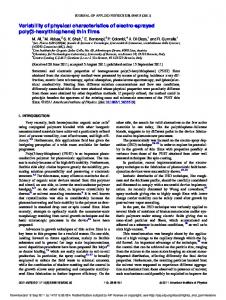
Figure 3. Simulation of three typical filters, complementary cyan, magenta and yellow, created by a stack of 16 alternating TiO2 and SiO2 thin films. Each layer is ¼ of a wavelength thick [5]. This simulation was done using TFCalc software. 2.1.4
Filter thickness
The physical thickness range for a single quarter wave layer will be in the order of 80 nm depending on the actual wavelength and index, therefore a complete filter will have a thickness of about 1 μm. A yellow filter will be slightly thinner because it is designed to reflect blue light which has a shorter wavelength compared to a cyan filter which is designed to reflect red which has a longer wavelength. 2.1.5
Computer simulations
In reality it is to difficult and time consuming to design and simulate thin film stacks manually. This is why a computer simulation is mandatory. In this thesis TFCalc from Software Spectra, Inc. was extensively used as a tool to simulate the transmission change under the influence of the etching. A number of parameters can be set in this software such as refractive index, thickness and absorption of each layer, also as a function of wavelength (dispersion). These simulations can be matched to fit the measured thin film filter. There are other parameters as well - polarisation and incident angle - but they are not used in the calculations of these cases, since the angle incidence is perpendicular to the substrate.
12
Theoretical background
2.2 Thin film processes There is a wide variety of methods to manufacture thin films in the thickness range of 0.05-5 μm. In this thesis only physical vapour deposition (PVD) with electron beam evaporation was used (see chapter 2.2.3.3) but other methods are briefly described below. 2.2.1
Sol-gel
Sol-gel is a wet chemical method where a thin liquid gel is applied on a surface and then solidified by a thermal process [6]. This wet chemical process is not common for the production of optical filters, but there are some interests in this area [7, 8]. The most limiting issue is that each substrate has to be processed individually, which makes the production inefficient. 2.2.2
Chemical vapour deposition
Chemical vapour deposition, (CVD) is a very frequently used method for the production of coatings in the semiconductor industry [9]. Different gas compounds inserted in a reactor tank under low pressure and sometimes in presence of electric field will cause chemical reactions that will grow a desired thin film on a substrate. Semiconducting materials, oxides and nitrides can be deposited. The reaction product is deposited on a selected substrate and very pure and crystalline coatings are possible. This method is not used for production of interference filters because of limitations in the reaction products which can be made. One very interesting thin film type is the growth of diamond like coatings which is possible at a substantial rate and thickness for protection of optics [10]. 2.2.3
Physical vapour deposition
The overwhelmingly most common process in order to produce interference filters is by Physical Vapour Deposition (PVD). This is a general term which involves all types of processes in vacuum where the source material is vaporized and transported by thermal motion to a substrate where it will condense in solid phase. The process is performed under high vacuum and the mean free path for the vaporized particle is longer than the distance between the source and the substrate [11]. This means that the vaporized particle will not collide with any gas particle before it hits the substrate surface where it condensates.
13
Theoretical background
The mean free path l can be described as:
(2.8) where k is Boltzmann‟s constant, T is the temperature, d is the molecule diameter and p is the pressure. For room temperature the mean free path of air is 5 meters at 10-5 Torr. This is a quite common process pressure. The substrate temperature has to be low enough otherwise the deposited material will re-evaporate. This is usually called the sticking coefficient [12]. Under most process conditions this is of little concern since a common process temperature of the substrate is in the 25-400 °C range and most oxides have a melting point far beyond this temperature. There are however some materials such as ZnS which have a low sticking coefficient [13]. It can bounce off the substrate surface even if the melting point is much higher than the surface temperature. It can be explained by the fact that there is a short time where the particle behaves as an ad-atom or ad-particle and has not had time to bond to the substrate. It takes a short time before the particle settles down. Therefore it can re-evaporate from the thermodynamically unfavourable state as an adatom. This sticking coefficient is possible to detect even for SiO2 and TiO2 on cold substrates, especially in the beginning of the deposition when the coating material sticks to the substrate and not to its own particles. PVD can be divided into several sub groups and variations such as sputtering, laser ablation, thermal evaporation and electron-beam deposition and a few other more or less exotic methods. The difference between them is the way the source material is vaporized and how it condenses. 2.2.3.1
Sputtering
By ionizing an inert gas and accelerating the ions towards a solid surface or target, it can knock off particles; this is called sputtering. This is done from a solid phase directly into the gas phase like sublimation. The particles will condensate on a closely placed substrate. Energizing can be done by having a slight amount of background gas in the range of 1-10 mTorr where plasma is created by an electric field in the range of 100-400 volts. More efficient sputtering is achieved by applying a magnetic field which traps electrons in the plasma so more argon atoms are ionized and accelerated towards the target.
14
Theoretical background
It is possible to insert a small amount of oxygen in the process. This leads to oxidation of the deposited thin film. Other process gases can also be added to give other compounds for example nitrides. In DC-magnetron sputtering it is only possible to sputter metals or conductive materials such as aluminium or titanium. Added oxygen will result in metal oxide thin films. By using a RF-magnetron it is possible to directly sputter dielectric compounds, however this process is rather difficult to master. There are several variations to sputtering but it is difficult to control the process and achieve uniform coatings. This is why this method seldom is used for filter production. However, very dense and hard coatings are possible. 2.2.3.2
Thermal evaporation
This is the simplest type of evaporation and has been used in the industry since the „30s. The first important application was antireflective coatings where MgF2 was extensively used since it is easy evaporated. Development of optical instruments for military application was a driving force. The evaporation is done by simply feeding electric current through a source in the shape of a boat made out of metal. Normally this source is made of tungsten, molybdenum or tantalum. There are some limitations; only a few types of dielectric materials can be evaporated, for example MgF2, SiO, ZnS and the boats are outworn after a few evaporations. It is not possible to evaporate SiO2 and TiO2 because of the high melting point of these oxides. However, this method is very simple and reliable [14]. 2.2.3.3
Electron beam evaporation
In most cases e-beam deposition is the preferred way to manufacture optical filters, and this thesis is aimed at thin films made by electron beam deposition [15]. An e-beam based system consists of a vacuum chamber and a source which can be heated by a powerful electron gun. Usually the acceleration voltage is in the range of 5-10 kV. By cooling the crucible with water it is possible to heat all types of material until it evaporates. Even difficult materials such as tungsten and carbon can be evaporated, although this demands temperatures in the range of 3000 °C or more. This can be done due to the fact that the e-gun has no thermal limit. The only limit is the way the source is placed and cooled.
15
Theoretical background
The electron beam source is based on the same principle as the e-gun in a cathode ray tube. A glowing tungsten filament is emitting electrons which are accelerated by an electric field. The current can be up to 1 ampere. When these energized electrons impact a target they lose their kinetic energy and because of the high current density it is possible to focus large quantity of energy in a small area. By efficient water cooling of the crucible only the source material will melt and not the crucible itself. If there was no water cooling the crucible would be evaporated, contaminating the coating. By bending the electron beam in a magnet field, usually in a 270° trajectory, tungsten contamination can be avoided since tungsten particles will not be bended by the magnetic field due to their heavy mass. This makes e-beam evaporation a very clean method and high purity coatings are possible. The source material SiO2, TiO2 or other compounds in Figure 4 are bombarded by electrons (j) from the e-gun (b). When it has melted and there is enough vapour pressure it will evaporate. Not shown in the image is a shutter which will allow evaporation material to reach the substrates in a controlled way. In order to monitor the thickness and the process rate, two methods are used. A quartz crystal (d) which oscillates at a resonance frequency of 6 MHz is exposed to the evaporation and material will condensate on its surface. This changes the resonance frequency slightly and allows monitoring of the process rate in the range down to ca 0.1Å/s. The crystal can only measure the physical thickness of the thin film, therefore an optical monitor is also viewing the process [16]. A beam of light (g) is reflected on a witness glass (h). Thereby the amount of reflected light can be analyzed by a monochromator and by the interference in the coating it is possible to calculate the optical thickness of the reflection. This has to be done on a separate fixed position since the substrates (f) are placed on planetary rotating devices which make it difficult to measure the optical thickness directly on the substrates. In order to get hard dense coatings the process has to be at an elevated temperature. Infrared radiation sources (i) with a reflector are aimed at the substrates to reach temperatures over 300 OC.
16
Theoretical background
Figure 4. PVD coating plant with e-beam. (a) vacuum chamber, (b) electron gun, (c) evaporation plume, (d) quartz crystal thickness monitor, (e) coated surface, (f) substrate (g) light path for optical monitor (h) witness glass for thickness monitoring, (i) heating radiation source, (j) electron beam path. 2.2.4
Thin film growth and nucleation
The growth of thin film oxides by PVD depends on several parameters. The evaporation rate of the source, substrate temperature, background oxygen pressure and crystal orientation of the substrate and a few other parameters will affect the properties of the thin film. 2.2.4.1
Nucleation
The nucleation of a vaporized particle on a substrate is caused by loss of energy and bonding to the surface. When a hot particle hits the substrate surface it will not stick immediately. For a moment it will be a rather mobile particle called ad-atom or ad-particle before it condensates and chemically bonds to the surface. While it is a mobile particle it can glide around until it reaches a thermodynamic favourable position where it condensates. This is usually a nucleation site, which could be a defect or some local crystallographic orientation. In the case of PVD at temperatures around 300 °C, there will be no mono crystal growth but more amorphous or nm-sized crystals. The growth of the film is usually columnar in structure, but depends heavily on the initial surface, nucleation and substrate temperature.
17
Theoretical background
For metal oxides the coating tends to be rather porous if deposited at room temperature because the ad-particle will lose its energy quickly and freeze in its position. By raising the substrate temperature the time where the particle acts as an ad-atom will be longer due to the fact that energy is added to the surface. There will be more time for it to find thermodynamically better positions to bond to. This leads to a more compact and dense coating. MgF2 coatings are a good example since it will be a dust layer easily wiped away by the thumb at room temperature, but by raising the substrate temperature it can be deposited as a dense and hard coating. 2.2.4.2
Epitaxial growth
In epitaxial growth a single crystal atom layer is formed one at a time. This can be done by growth on a substrate which has a matching crystal lattice constant and at very high temperatures. 2.2.4.3
Ion beam assisted deposition
It is possible to add energy to the surface by an ion source by bombarding the surface with Ar-ions under the deposition process [17]. Ion Beam Assisted deposition (IBAD) can give very dense and hard coatings even at low substrate temperatures. It is possible to produce hard coatings on plastic and heat sensitive optics. 2.2.4.4
Background oxygen
When some materials are evaporated they tend to dissociate, ZnS will dissociate completely into Zn and S (g) but recombines into ZnS on the substrate. Some oxides are problematic because they dissociate in the melt but do not recombine on the substrate. TiO2 will decompose slowly into its most stable form, Ti3O5, in the melt. The released oxygen is not enough to re-oxidize TiO2 on the surface. In order to get fully oxidized TiO2, oxygen back pressure in the range of 10-4 Torr is needed as a background pressure. Oxygen will constantly impact the surface and it is possible to achieve a fully oxidized film. SiO2 also has this tendency to lose oxygen under evaporation but is not as problematic as TiO2. 2.2.4.5
Deposition rate
It would be desirable to have as high deposition rate as possible because of production costs. Depending on what oxide is used and the amount of oxidation needed there is a reaction limit to the process rate. For TiO2 it is in the range of 2-5Å/sec. Otherwise it will not be fully oxidized. SiO2 can be deposited at slightly higher rate, ca 10Å/s. Even if it would be possible to evaporate at much higher rate the coating will be less dense. It is also difficult to have good endpoint detection and control of the thickness if the rate is too high.
18
Theoretical background
2.3 Lithography In most types of pattern generation, photolithography is involved. When a newspaper is printed, or when an integrated circuit is fabricated, photolithography is a major part of the processes. The word is derived from Greek and means literary “write on stone”. In the beginning of the printing era, text and pattern were engraved on stones. A thin film of ink was covered on the top of the pattern and then pressed on paper to produce a copy. Multiple copies could then be produced. In modern printing, the engraving is not done on stone but is done by light sensitive photoresist were the pattern has been engraved by exposure of UV-light. When a thin film surface will be pattered, there are several steps involved. The first step is to create a mask which consists of the original pattern. This mask consists of a thin layer of a patterned metal coated on a substrate of glass or plastic sheet. The pattern of the mask is projected on the top of a photoresist coated substrate with the thin film (see Figure 5). The photoresist is sensitive to UV light. After the exposure, the exposed parts will be dissolved in a developer. The underlying parts of the thin film will, after development, be exposed to an etching agent which dissolves this thin film area and leaves an identical copy of the original mask [18].
Figure 5. Lithographic process in four steps for positive photoresist.
19
Theoretical background 2.3.1
Photoresist
There are two types of photoresist: negative and positive resist. Positive resist which is used in this thesis will give a positive image of the original pattern where negative resist will invert the image. This is due to the fact that the exposed area of positive resist will dissolve in the developer while the exposed area of negative resists hardens and will not dissolve, only the parts which are un-exposed by UV light are dissolved in the developer. The difference is due to different types of photo-induced chemical reactions involved. Most types of photoresists have a limited working range of temperature and room temperature processes are preferred. 2.3.1.1
Negative photoresist
Negative resists are often based on photo induced cross-linking of short polymer chains, this decreases the solubility in alkaline solution. This type is not as common as positive resist but in some cases it is possible to achieve higher resolution compared to positive photoresist. 2.3.1.2
Positive resist
Positive photoresists are sensitive to the wide band UV and blue light and are usually based on novolak and diazonaphthoquinones. The resists used in this thesis are based on these compounds. 2.3.1.3
Novolak resins
Novolak (N) or phenol-formaldehyde-resin can be manufactured by both a base and acid catalyzed condensation reaction with phenol and formaldehyde. Acid catalyzed polymerization promotes linear polymers with reaction on the ortoposition on the phenol (see Figure 6). A slightly unbalanced molar ratio between phenol/formaldehyde which is 9.5 there is passivation. 2.11.2 Al2O3
Al2O3 has a refractive index of 1.62 at 600 nm when deposited at 300 °C [67]. It has very little absorption in the range from 200 nm to 7 um. It dissociates very little under evaporation but some oxygen back pressure in the chamber can be beneficial. It must be evaporated from an e-gun. It can produce very dense hard layer with almost 100% packing density [68]. The thin film has very good adhesion to silver but if it is used as protective coating SiO2 or some other moisture barrier must be on top because Al2O3 act as a very bad moisture barrier [69]. Al2O3 is an amphoteric oxide and it is possible to dissolve it in both acid and basic solutions (see Figure 18).
41
Theoretical background
Figure 18. Pourbaix diagram of Al at 1 mM. As seen Al2O3 is stable between pH 4-11. In reality amorphous Al2O3 does only dissolve in HF and phosphoric acid but not in H2SO4. Also it does not dissolve in 30% NaOH. Crystalline Sapphire annealed at >1000 °C is not soluble in HF [70]. The only important oxidation state is III. Oxidation state II has been observed in high altitude grenade explosion residue by aluminium containing explosives [71]. 2.11.3 TiO2
Ti, Zr and Hf belong to the same group and have a successively larger mass. With Ti as the lightest atom, they all share similar chemical properties. TiO 2 is a very popular high index material and is frequently used in almost all kind of optical filters. The refractive index is 2.2-2.42 depending on process conditions [72]. It is transparent in the visible, but shows slight absorption in Near UV and IR especially if Ti is not fully oxidized to IV and is therefore most suitable in visible applications. It is easily evaporated from an e-gun but dissociate heavily to the most stable form which is Ti3O5 [73]. The TiO2 melts completely in an egun crucible and it is common to use an insulating liner of molybdenum to contain the melt. In order to re-oxidize the evaporated oxide into its oxidation state IV an oxygen background pressure is introduced in the process.
42
Theoretical background
TiO2 is an amphoteric oxide which means it is soluble in acids and bases (see Figure 19) [74]. It can occur naturally in three different crystal forms: rutile, brookite and anatase [75]. There are several oxidation states for Ti: 4, 3 and 2 but the most common is IV and only oxidation state IV gives colourless compounds. Oxidation state I has been observed as TiH in hollow cathode lamps [76]. It is easy dissolved in boiling Sulphuric acid [77] and by catalytic etching with H2O2 as mentioned in chapter 2.4.4.
Figure 19. Pourbaix diagram of Ti at 1 uM [42]. In reality a thin film TiO2 is very difficult to wet etch if it is deposited on substrates at >300 °C. In that case the most frequently used methods are various kinds of plasma etching techniques where etching rate up to 2000 Å/min is possible [78]. 2.11.4 ZrO2
ZrO2 has a refractive index of ca 1.95 and a low absorption from 250 nm-10 μm. It slightly dissociates under e-beam evaporation, so background O2 pressure is important in order to grow non absorbing coatings. It is preferably evaporated by an e-beam source from a graphite liner where it melts [79].
43
Theoretical background
Hf is always present in findings of Zr. Zr metal have a thin ZrO2 passivation layer which is even more efficient than TiO2. This is why Zr is very popular in alloys in demanding applications such as in nuclear reactors where it withstands corrosion very well. The oxide is amphoteric (see Figure 20).
Figure 20. Zr Pourbaix diagram at 1μM. ZrO2 thin films tend to be inhomogeneous but can be stabilized by adding some other oxide. It can be made more stable with small amounts of Y2O3 in the coating, yttiria-stabilized zirconia (YSZ). This compound is of interest in corrosion resistant coatings [80]. IV is the common oxidation state but III and II exist also. Some successful etchings have been achieved by MOCVD techniques [78]. The etching mechanism is explained by HF attack on the surface Zr-OH bonds leaving a Zr-F bond and H2O. The etching rate is rather low, at best 450 Å/min on MOCVD deposited ZrO2 [81]. Zr metal is resistant in boiling H2SO4 at less than 70% concentration and in HF [82]. Boiling 20% HCl can attack Zr metal. It should be noted that thin Zr films behaves differently compared to bulk Zr.
44
Theoretical background 2.11.5 HfO2
Hf was discovered as late as in 1922. HfO2 is interesting as a high index material for UV filter applications since the absorption is low down to ca 220 nm. The refractive index is ca 1.9 at 500 nm. The refractive index is 2.15 at 250 nm and 250 °C substrate temperature. The coating is fairly hard. The most dominant oxidation state is IV. HfO2 is amphoteric but more alkaline compared to TiO2 (see Figure 21). HfO2 must be melted carefully in a liner to avoid tunnelling, see 2.11.7 and will slightly dissociate, so therefore a slight background O2 pressure is needed to get fully oxidized and absorption free HfO2 coatings. At low substrate temperatures the coating is porous and it is recommended to evaporate under elevated temperature conditions in order to get high packing density [83].
Figure 21. Pourbaix diagram of Hf at 1 uM. Very little is mentioned about solubility in the literature but it is probably slightly tougher against attack compared to Ti. Since Ti can be dissolved in boiling H2SO4 it is likely Hf should be that also. There have been some studies by wet etching of HfO2 since it is an interesting replacement for SiO2 as gate material in semiconductors. Some success has been achieved in etching MOCVD deposited HfO2 films were etching rates up to 178 Å/min has been recorded in HF solutions [81]. It should be noted that the material can behave completely different under other deposition conditions.
45
Theoretical background 2.11.6 Y2O3
Y2O3 is an intermediate index material with refractive index of 1.8 at 550 nm and it is useful from 300 nm-14 μm. It has to be evaporated from a graphite liner where is sublimes, and it behaves like most other oxides by dissociating slightly when evaporated [84]. The oxidation state is exclusively III [85]. Y2O3 is an amphoteric oxide slightly more alkaline and should be soluble in acids [86].
Figure 22. Pourbaix diagram of Y at 100 mM. As shown in Figure 22 the concentration is very high with a wide pH range of soluble ions. This could be an indication that it actually is slightly easier to dissolve the oxide in acid compared to TiO2. The Pourbaix diagrams for Ti, Zr and Hf are simulated at much lower concentrations, 1 μM still with very limited pH range. Very little is mentioned in the literature of the etchability of Y2O3 for thin films.
46
Theoretical background 2.11.7 SiO2
SiO2 is extensively used as a low index material in many applications. Its refractive index is 1.46 at 550 nm and can be made transparent from 200 nm - 3 um as a thin film. It is completely amorphous and must be evaporated by an egun. I will slightly dissociate but it is not always necessary to add oxygen in the coating process. It will sublimate and the source is subjected to problematic tunnelling when evaporated, this means the e-beam digs a hole in the SiO2 and makes evaporation uneven [87, 88, 89]. SiO2 is an acidic oxide indicating it is soluble in alkaline solution, (see Figure 23A). It can be dissolved by boiling NaOH giving a Na2SiO3 solution. It is soluble both in HF and in alkaline solutions [90]. The HF chemistry is very well known due to the massive use in the semiconductor industry as mentioned in chapter 2.4.2. Oxidation state 4 is the most stable but oxidation state II also exist as SiO. This has also been used as coating material since SiO is easier to evaporate form a thermal source. The disadvantage is a slight absorption in blue. Etching rate can be as high as 1500 nm/min in 10:1 solution of HF for CVD type SiO2. The solubility of Si increases dramatically when fluoride compounds are added at low pH (see Figure 23B). Fused quartz has an etching rate of 26 nm/min [91].
Figure 23. Solubility of Si at 1mM (A) and solubility when [F]=100mM is present (B). Note the soluble SiF62- in the region pH 0-5. SiO2 is even slightly soluble in cold water, 11 ppm at 25 °C, however this is a very slow process, mostly of interest in a geological perspective [92]. Etching of silicon can be used by a mixture of nitric acid and HF. The nitric acid oxidizes Si into SiO2 which is soluble in HF. A pure HF-solution does not etch Si, therefore this is a very good selective etch in cases were it is of interest to etch SiO2 coatings on a silicon wafer and the underlying Si substrate should not be damaged.
47
Theoretical background 2.11.8 MgF2
MgF2 is one of the lowest index materials making it very popular in anti reflective coatings. It has a refractive index of about 1.39 when deposit at 300 °C. This results in rather hard and dense coatings. Deposition at room temperature results in very porous and useless films easily wiped off with a finger. It has very good UV-transmission down to 120 nm and is transparent up to 7 um. Evaporation is easily done in a thermally heated tungsten boat, but can be evaporated by e-beam [93]. One major disadvantage for MgF2 films is the high tensile stress making it difficult to produce multilayer coatings. It is not possible to simulate MgF2 and create Pourbaix diagrams due to lack of solubility data. The solubility for MgCl2 is 72.7 g/100 ml compared to zero for MgF2. This huge difference between the chloride and fluoride is probably due to the difference in ion size and stronger Mg-F bonding. It is also soluble in HNO3 and slightly in acids [94].
48
Results
3 Experiment 3.1 Production of the thin films All thin films were produced by PVD with in a BAK 550 box coater with a planetary system. Evaporation of the materials was done by an electron beam gun. The samples were manufactured in fall 2008 in Lint, Belgium (see Figure 24). The thin films were deposited on polished Si wafers and 1 mm thick borofloat glass from Schott. For the stress measurements, 0.1 mm thick borofloat glass was used as substrates. In each batch, all three substrates were coated simultaneously. The layers were made relatively thick, 2000-5000 Å, in order to make the etching observations easier and to be able to find the refractive index and thickness TP.
Figure 24. A retrofitted Balzers BAK 550 box coater with completely new interior and computer controller. All coatings used in this thesis were produced by this machine. 10 different samples were fabricated in the first series. Identity T1 compounds TiO2
S1 S2 Z1 SiO2/Al SiO2/Al ZrO2
Z2 ZrO2
Y1 Y2O3
Table 1. Compounds grown in the first test series.
49
H1 HfO2
A1 Al2O3
M1 MgO
MF1 MgF2
Results
All 10 thin films were grown at a substrate temperature of 325 °C. The evaporation properties differed slightly among them, but the best known evaporation parameters were used shown Table A1. The thin films S1 and S2 were grown with an 80 Å thick aluminium interface layer as an endpoint layer for easier etch rate determination. Five additional complete magenta filters were also fabricated, M200-M325 processed at substrate temperatures between 200–325 °C. These filters were fabricated at relatively high O2 pressure. Another magenta filter called N250 was also added in the study. This was processed at lower oxygen pressure at 250 °C. from a standard production batch in the late 2009. The N250 filter was used in the later stage of the study to evaluate etching performance.
3.2 Physical characterization of the thin films The 10 different single layer thin films in the first series produced at the late 2008 were characterized by ellipsometry and by transmission spectral curve fitting, respectively. The refractive index n, physical thickness TP, thermal behaviour and stress were thus evaluated. 3.2.1
Ellipsometric measurements
The ellipsometric measurements were done on a SE-400 Sentech instruments equipped with a HeNe-laser which generates light at a wavelength of 632 nm. For each measurement, three different incident angles were selected for the laser thereafter computer software calculated the most probable reflective index and thickness. It was very important to keep the surface as flat as possible and the alignment of the substrate was critical. Measurements were done only on the thin films deposited on Si-wafers. Coating S1 and S2 could not be measured because both contained aluminium layers underneath. 3.2.2
Transmission spectra
By the measurements from a spectrophotometer in the range of 200-900 nm, it was possible to make curve fitting for each coating in order to match a simulated curve from the TFCalc software. The curve fitting models were optimized around 500 nm and the surrounding wavelengths were not fitted equally well due to the dispersions of the thin films. The information was still enough to find the thickness TP. This method resulted in more reliable values compared to the ellipsometric measurements. It was also possible to extract dispersion data but these calculations were not done.
50
Results 3.2.3
Surface profilometry
The physical thickness was measured by a Tencor Alphastep 200 stylus profilometer. In order to measure the TP, some minor areas of the Si wafers was covered by pieces of thin aluminium foil during deposition. Thereafter the aluminium pieces were removed, creating sharp edges on the thin films. The stylus could then travel over these edges to find the TP. Because this instrument was not well-calibrated, this part of the measurements was not carried out for all the thin films. Only three measurements were done on Y1 and one measurement on Z2. 3.2.4
Thin film stress
Borofloat glasses with a thickness of 0.11 mm and 48 mm in diameter were coated with the selected compounds from Table 1. By observing the resulting curvature, it was possible to measure the internal stress of the films. A very simple setup was used where the test pieces were placed in front of a pinhole with a cross mark. By observations through the pinhole at different distances to the substrate, it was easy to find the radius of curvature of the substrate. The surface stress caused a curvature of the substrate and created a focal point. This focal point could easily be found by the pinhole. By turning the substrate, so a concave surface always was directed towards the pinhole, both compressive and tensile stress could then be measured. 3.2.5
Thermal shift
In order to measure the thermal shift, two spectra were taken from each coating. The first spectrum was taken at room temperature. After that the sample was heated to 300-320 °C, the second spectrum was then taken 10 minutes after this condition has reached. The spectral shift caused by the heating was recorded. This gave a rough indication about the thermal stability of the filter. In the case of a multilayer filter, the shift was measured at a point in the spectrum where the transmission was at 50 % at the right cut-off. In the case of a single layer filter, the shift was measured from a local minima and a local maxima point.
51
Results 3.2.5.1
Thermal shift of single layers
This test was done in order to see if there were any differences in thermal shift between T1 and S1. The same type of spectra as shown in attachment Figure A9 and A10 were recorded at room temperature. Thereafter the samples were heated to 320 °C for 10 minutes. The peak waves λP shifted after the heating procedure and was recorded, giving the thermal shift values. The observed shift from each measured peak from 419-810 nm was normalized to 600 nm for easy comparisons. 3.2.5.2
Post thermal annealing
The Drix M200-M325 and N250 magenta samples were thermally treated in order to see if post annealing could improve the long term thermal stability. Even if the material was un-etchable after post annealing, this test could reveal the possibility of future improvements for etchable thin films. The tests were performed by measuring the thermal shift before and after a heat treatment in an oven for a specific period of time. The change of thermal shift was then recorded. First test One M325 sample was first measured at the starting period and then placed in an oven set at 500 °C. Before each shift measurement, the sample was allowed to cool down to room temperature. The thermal shift was measured at 320 °C after 10 minutes of heating. The resulting values were not normalized since the shift was close to 600 nm. 6 measurements were taken under a period of 144 hours. The time for the samples to cool down before each measurement was not specified in this test and could vary. Second test In order to get a more consistent reading, samples from M250 and M325 were baked at 420 and 500 °C for up to 148 hours. All samples were cooled down and soaked in de-ionized water at 20 °C for a couple of minutes and then blown dry with pressurized air prior each measurement. The data were taken on both 50% transmission flanks on the spectra around 460 and 630 nm. Values were normalized at 600 nm. Third test Even more care was taken in this test compared to the first and second test. It was performed around 12 November 2009 and it was done with one from the latest magenta production, N250, containing lower oxygen pressure in the coating process.
52
Results
The post annealing was done at 350 °C for 36 hours. Prior to each shift test, the material was settled to room temperature then soaked in water for at least 10 minute then blown dried in pressurized air and let standing in air for 3 hours before each measurements. A spectrum was recorded and the sample was heated to 300 °C for 10 minutes before each reading. The shift was normalized at 600 nm.
3.3 The in-situ etching instrument A simple but reliable etch cell was constructed of PMMA. The complete instrument can be viewed in Figure 25. The inside width of the etching cell was 10 mm and the sample was placed in the centre by a holder in the lid. It was then possible to quickly insert the sample in the cell filled with etching liquid. A fibre spectrometer of the type Ocean optics USB2000 was used with a multimode fibre with a numerical aperture of 0.22. The distance from the tip of the fibre to the thin film surface was 20 mm which gave an active measurement diameter of 9.7 mm on the sample. It was difficult to have any smaller area due to the construction but it was believed that the etching uniformity was at an acceptable range.
Figure 25. The etching cell. A 12 V power supply (A) is connected to a halogen lamp (B), this illuminates a diffuser (C) in order to get uniform light, slightly seen as a square, In the middle the etching cell (E) with lid (D). The optical fibre (G) is pushed as close as possible to the etching cell window and is connected to a fibre spectrometer (H) and a computer with software for sampling of spectra (I). A removable cover (F) protects the measurement form stray light.
53
Results
The inner dimension of the etch cell was 41x10x56 mm giving a volume of 22.9 cm3. The total thickness of the cell was 16 mm.
3.4 Etching tests 3.4.1
Etching tests of multilayer coatings
The M225-M325 and the N250 magenta filters were evaluated in terms of etchability in 3% HF. 3.4.1.1
HF etching of magenta filters
An etching test with 3% HF was used to evaluate the five different magenta samples, M225 to M325. The etching time of a complete filter was determined by visual observations. The etching behaviour was also observed. 3.4.1.2
In-situ etching measurement vs simulation
A series of spectra were recorded at a sampling frequency of 0.5Hz from 400900 nm under a complete etching sequence of the magenta filter N250 in 3% HF solution. The idea behind this experiment was to evaluate whether it was possible to simulate matching spectra for a complete etching sequence or not. The simulation model was done by TFcalc by calculating 19 different thin films with one top layer removed for each simulation. This would then correspond to an assumption that the real etching would remove one layer at a time. 3.4.2
Etching test of single layer oxides
The single layer coatings, both on borofloat and Si wafers from the first test series (see Table 1), were cut in small pieces about 2x2cm in side. These pieces were tested in a wide variety of etchants. 3.4.2.1
TiO2, HfO2 and ZrO2
All three oxides from group IVB was evaluated in such a way that it was possible to make comparisons among them. First test T1, H1 and Z2 coated on borofloat glass were exposed for 10 minutes to 77 % H2SO4 at a temperature of 170 °C in a reflux boiler. Visual inspections were made in order to analyze the etching result. Glass substrate could be used since this did not dissolve in the etchant.
54
Results
Second test The three samples of T1, H1 and Z2 were exposed for 30 min in 77% H2SO4 at a temperature of 96 °C. Spectra were taken both before and after etching and the wavelength shift was noted in order to calculate the amount of material etched away. The etchant was heated in a boiling water bath. HF etching 1) 3% HF solution was used on Z2 and H1 coated on Si-wafers and visual observations were made. An etching test with 5% HF solution was performed on T1 coated on Si-wafer for comparison. 2) Concentrated HF (47%) was tested on Z2, T1 and H1 on silicon substrate and visual observations were made. Catalytic etching of TiO2 T1 (TiO2) on glass was tested by catalytic etching in 9 different solutions containing 10 ml 34% H2O2 and 0, 0.1, 0.2, 0.5, 1, 2, 4, 5, and 10 ml conc. HN3 in each solution. Water was added to give 20 ml total volume in each solution. The pH was measured with a calibrated standard pH-glass electrode. Etching time was 6 minutes for all samples. Since the solution rapidly decomposed, it was impossible to etch through the whole coating. Spectra were taken before and after each etching test and the etching rate was calculated from the measured spectral shift caused by the changed thickness of the thin film. Catalytic etching of ZrO2 and HfO2 One sample from T1, Z2 and H1 coated on Si-wafers were etched for 2 hours in a solution consisted of 34 % H2O2, conc. NH3 and H2O in a ratio of 2:1:1. Visual observations of the etching were made. 3.4.2.2
SiO2
First Test Because SiO2 have an index close to the borofloat substrate index, a very thin layer of Al ca 80 Å thick with a transmittance in the range of 20-70% was present between the substrate and the SiO2 coating. This improved the spectral reading. One S2 sample was etched in 3% HF for 5 seconds. The coating was quickly dipped in the solution thereafter quickly rinsed with water. One spectrum was taken before the etching and one after. Spectra were taken when the coating was dry. The reason for this procedure was that water with a refractive index of 1.33 makes the interference weaker on the thin film. The measurements in air improved the measurements.
55
Results
Second Test One sample of S2 was etched by 3 % HF solution for 19 s. The etching was recorded in-situ and the sampling frequency was 1 Hz for the spectra. Nine of the most interesting curves were selected for the analysis. Third Test A sample of the S2 coating on borofloat glass was etched in 0.5% HF solution. The etching time was measured by visual observations. Fourth test This test was done to show the difference in morphology between the aluminium layers from the S2 coating and a sputtered standard aluminium coating. A 5000 Å thick coating from Drix was etched in a 2 % HF solution. The etching rate was calculated from visual observation. Fifth test A sample of the S2 coating on borofloat glass was baked at 500 °C for one day in an oven. Visual observation was made. 3.4.2.3
MgO
First test A M1 sample was etched in 6.0 M H2SO4 solution and the etching time was measured. One sample was post baked in an oven for 24h at 500 °C and the etch time was measured. Both tests were performed on borofloat glass. Second test M1 coated on borofloat glass was used as a case example for the evaluation of the in-situ etching instrument. A sample of MgO was etched in a 3.0 M H2SO4 solution and several spectra was recorded with a sampling frequency of 0.5 Hz. Five different transmission curves were selected. By comparing the measured curves with the simulated curves from the TFCalc software, the thickness could be calculated and the etch rate could be determined at 4, 8, 12, and 16 seconds.
56
Results 3.4.2.4
Y2O3
First test Several different acids were tested on Y1 coatings on Si wafers. One sample was tested in 20 % HF solution. Y1 was also etched under hydrochloric acid (HCl) of two different concentrations, 4 and 0.3 M, respectively, in order to see if the etching rate had a linear relationship with the concentrations. 6.0 M H2SO4, 3% HF and 6.0 M NaOH solutions were also tested. In all these tests, the etching rate was recorded by visual observations. Second test It was discovered that the presence of HF in the etchant inhibits the reaction on Y2O3. Therefore, a test was performed in order to see how the etching rate was inhibited by HF. Three different concentrations of HF at 0, 0.24 and 0.48 % with 2.0 M HCl was used in a etching test on Y1 coated on Si-wafer. Visual observations of the etching time were made. Third test The idea behind this test was to see if the HF would form some compound with the Y2O3 surface preventing further etching in acid. One sample of Y1 coating on Si wafer was treated with concentrated HF for 60 seconds. The sample was rinsed with water then etched in 2.0 M H2SO4. The etching time was recorded. One sample was etched directly in 2.0 M H2SO4 and the etching times were compared. 3.4.2.5
MgF2
Samples of MF1 coated on Si wafers were etched with 6.0 M H2SO4 for 20 minutes, concentrated HF and 6.88 M NaOH for 5 minutes, all done at room temperature. 3.4.2.6
Al2O3
Samples of A1 were exposed to concentrated H2SO4 at room temperature and to 57 % H2SO4 at 85 °C for 13 minutes. A1 was etched with concentrated HF and BHF where etch time was observed. A peroxide etching test was made on one A1 sample with an etchant consisted of 34 % H2O2, concentrated NH3 and H2O in a ratio of 2:1:2. A sample of A1 was etched with 5.88 M NaOH and observations were made. A1 was coated on Si wafers in all these tests.
57
Results
3.5 Etch matching of Y2O3/SiO2 The discovery that HF inhibits the etching process of Y2O3 in an acidic solution gave the idea to find a matching pair of oxides with equal etching rates. Since the etching rate of Y2O3 reduces when increasing the HF concentration (See section 4.2.3.4 Second test) and the etching rate of SiO2 increases linearly with the HF concentration (see section 4.2.3.2, third test), there should exist a concentration point where they both intersect. The idea behind this experiment was to find this concentration point. Six different solutions of different concentrations of HF at 0, 48, 96, 140, 190 and 240 mM were prepared and the concentrations of H2SO4 were 6.0 M. Six samples from S1 and six samples from Y1 coated on Si wafers were immersed into solutions of the individual concentrations and the etching time were recorded by visual observation. Two graphs were calculated from the knowledge of their thicknesses.
3.6 Etching rate of photoresist Two tests were performed on the photoresist, i.e. Fuji OIR908-35 2.5um spin coating. In general, positive photoresist withstand acids reasonably well, but it starts to dissolve in an alkaline solution. First test The goal of this experiment was to determine the alkaline pH limits in which photoresist starts to dissolve into the solution. In order to have a safe limit, the etching rate of the photoresist should not be faster than the etching rate of the underlying thin film. There should be enough safety margin in order to achieve good etch performance without undercutting. If the limit is set to 10 minutes exposure in the etchant, the acceptable etching rate of the photoresist would be 40 Å/sec before the etchant will reach the underlying coating which it is protecting. This value should only be considered as a guideline and a safety margin should be chosen. The samples were immersed in three solutions containing 96.5, 150 and 251 mM of NaOH under constant stirring. The setup was shielded from all UV light in order to avoid exposure of the photoresist. The time for complete dissolution of the photoresist was recorded. Second test One sample of photoresist was immersed in a concentrated NH3 solution and the behaviour of the photoresist was observed.
58
Results
4 Results and discussion 4.1 Characterisation of the thin films 4.1.1
Ellipsometric measurements
Ellpsometric measurements were more difficult to master when the thin films were too thick. Z1 was probably incorrect for this reason (see Table 2). Coating
index, n
Tp/Å
Remark Very stable
A1
Al2O3
1.642
5081
H1
Hf2O3
1.965
2760
Y1
Y2O3
1.77
4260
Very stable
Z1
ZrO2
1.979
10345
Uncertain
Z2
ZrO2
1.87
2420
Stable
MF1
MgF2
1.376
4364
Stable
MGO
MgO
1.714
4190
T1
TiO2
2.26
4644
Table 2. Ellipsometric results with physical thickness TP in Å. As mentioned in chapter 2.10.1 the thin films were assumed to have none absorbance and was only measured on Si-wafers. 4.1.2
Transmission spectral fitting
There was a sharp dip around 300-350 nm in the measured spectra (see attached Figures A1-A10). This did not make any difference in the curve fitting model since the fitting was done only at 500 nm. Coating A1 H1 Y1 Z1 Z2 MF1 M1 T1 S1 S2
Compound Al2O3 Hf2O3 Y2O3 ZrO2 ZrO2 MgF2 MgO TiO2 SiO2 SiO2
Index, n 1.64 2.01 1.79 1.86 1.97 1.38 1.71 2.35 1.46 1.46
TP /Å 5022 2748 4350 5524 2398 4529 4488 4487 7363 7020
Table 3. In these measurements the SiO2 thicknesses (S1 and S2) could be easily measured even though a thin aluminium layer was present.
59
Results
As seen in Table 3, most TP values are well-fitted within the ellipsometric measurement except Z1. It is believed the Z1 value is more reliable in the present fitting, see chapter 2.10.2. 4.1.3
Surface profilometry
The thickness of Y1 was measured three times with the resulting values of 4000, 4000 and 3900 Å.. Z1 was measured a single time with a thickness of 2200 Å. See chapter 2.7.3 for the theory behind this method. These values are considered as an aid to support the correct values for the spectral fitting. The values are in reasonable good proximity to the values estimated by the optical fitting method. 4.1.4
Thin film stress
The radius is positive if the substrate is concave and the thin film is faced towards the observer. A positive value leads to tensile stress, and a negative value compressive stress. The smaller the radius, the higher the stress level it will be. Material MgF2 MgO HfO2 TiO2 SiO2 (1) SiO2 (2) Al2O3 Y2O3 ZrO2 (1) ZrO2 (2)
MF1 M1 H1 T1 S1 S2 A1 Y1 Z1 Z2
radius/cm 50 -30 280 300 200 200 170 220 300 300
Table 4. Results from the thin film stress measurements. Most coatings showed weak tensile stress, see Table 4, but the radius was so large that was difficult to measure. The stress was believed to be in a range where multilayer coatings are possible to be made. There were no calculations done for the stress but equation 2.12 in chapter 2.9 can be used to find the values. MgF2 showed very strong tensile stress and should be avoided in multilayer coatings. MgO should also be avoided in multilayer coatings since it showed very strong compressive stress.
60
Results 4.1.5
Thermal shift
Since there was only one measurement from each of the samples in the post thermal annealing test (4.1.5.2) the results in this part were not statistically sounded. Therefore, the post annealing test, gave somewhat an unclear result, still showed an indication of thermal stability of the tested thin film materials. However, the measurements on several points in a single acquisition in the thermal shift for a single layer coating (4.1.5.1) gave a better statistical proof on each specimen. 4.1.5.1
Thermal shift single layer
The shift seemed to be the same over the whole visible spectra for both S1 and T1, but the shift in S1 coating were almost double in comparison to T1. S1 shift λP /nm
n-shift/nm
T1 shift λP /nm
Shift/nm
Shift/nm
n-shift/nm
419
15
21.5
438
6
8.2
464
16
20.7
474
6
7.6
509
17
20.0
525
9
10.3
595
18
18.2
589
12
12.2
655
24
22.0
679
14
12.4
810
15
(11.1)*
Average
20.5
10.1
Table 5. Thermal shift for SiO2 (S1) and TiO2 (T1). * The shift at 810 nm could be contributed to measurement error. The n-shift was the normalized value at 600nm. λP was the measured peek of the waves. The reason why the wavelengths reduced when heated could be explained by the evaporation of the absorbed water from the porous coatings and caused a lower refractive index. This could be an indication of the packing density of the coating. It seems that the TiO2 had a slightly better packing density compared to the SiO2. 4.1.5.2
Post thermal annealing
It proved to be very difficult to measure the post thermal annealing changes because small errors in handling of the samples could affect the measuring result. The first test was done on a very rudimentary basis, the second was a failure. But the results did show some interesting observations. The third and the last test were done with great care and with a much better precision.
61
Results
First test As seen in Figure 26, there is a clear trend in these measurements towards lower shift. It should be pointed out that there is no statistics involved, but there is a reason to believe that the trend is shifting to a low level with a longer baking time.
Figure 26. The graph shows a trend down with less thermal shift. In a 24 hour annealing test, it showed that the shift was completely reversible if it was measured again directly after being cooled down because the spectra got back to its original position. The long term post annealing seem to be irreversible probably due to change of the morphology in the coatings, see chapter 2.8. Second test There was no clear trend in this test and it was difficult to interpret the result from these measurements even though efforts have been made in order to improve the way the samples were handled. However, observations showed that the sample developed cracks on the thin film surface after 48 hours at 500 °C. Very fine microscopic fractures, around 0.5-1mm long in size, were found all over the surface. This finding is important since it indicates possible limitations at too high temperatures. Third test This was a more successful post annealing test.
62
Results
A very clear trend can be viewed in Figure 27 where the N250 coating showed improved thermal shift stability even after an hour post annealing period. The dramatically improvement in shift stability was due to changes in the thin film growth process or due to better handling of the sample, but the change is too large to be explained only by random statistics.
thermal shift N250
12
normalized shift/nm
10 8 6 4 2 0 0
5
10
15
20
25
30
35
40
time/h
Figure 27. Post annealing test for magenta filter N250.
4.2 Etch tests 4.2.1
HF etching of M225-M325 magenta filters
In all cases from sample M225 to M325 the SiO2 layers etched away quickly and left behind a residue of TiO2, which was more or less slowly etched away depended on the substrate temperature in the coating process. This correlates well with the TiO2 Pourbaix diagram in Figure 19 and the more easily soluble SiO2 Pourbaix diagram in Figure 23. coating M200 M250 M275 M300 M325
TS °C
T1/s
T2/s
λS /nm
200 250 275 300 325
8 10 10 16 22
30 30 110 Non etchable Non etchable
9.2 9.04 7.5 8.8 7.3
63
Results
Table 6. The wavelength shift λS is normalized at 600 nm and TS is the substrate temperature in the coating process. The data in Table 6 is showing the etching times T1 and T2. The time T1 corresponds to the point when there was only a grey soft residue left. The time T2 indicates the complete removal of all coating with no residue left. T1 could be interpreted as SiO2 etching time even though etchant are penetrating through the layers and therefore will not give corresponding etching rate for single layer SiO2. However, there is a clear trend in longer etching time for both T1 and T2 until sample M275 where the coating become very difficult to etch due to a huge etching rate difference between TiO2 and SiO2 that caused lots of grey residues. There would be no residue at all if the etching rate for SiO2 is equal to the etching rate for TiO2. But, this was never the case in any of the samples.
Figure 28. Magenta material M275. This photo was taken under the etching process where the thin film had begun to peel off. There is still some colour present in the filter indicating interference from SiO2/TiO2. The thermal shift λS in Table 6 was also measured. There is a trend indicating a slight improvement of thermal shift stability but there is a demand for achieving much lower shifts close to zero in order to have a stable filter. This was not the case even for the M325 material indicating post annealing is necessary. These measurements clearly highlight the etching problems for the filters. It was not possible to measure the in-situ etch spectra on these filter since the etching behaviour was so bad. 4.2.2
In-situ etching measurements of the N250 magenta filter
The two resulting graphs, one from the simulation (Figure 30) and one from the in-situ etching test (Figure 29) are compared with each other.
64
Results
Figure 29. This graph represents transmission through the layers for sample N250 Magenta filter. The number for each graph should be multiplied by 2 to get the time. Total etching time was 142 sec.
65
Results
Figure 30. Simulated spectra for an etching through 16 layers L1-L19, the number of curves is 19 because there were some double layer present. As seen in Figures 29 and 30, there is an efficient blocking of light from 470– 610 nm. In both simulation and measured filter, the effect of blocking slowly reduced until the etching was complete. The simulation shows reasonably good agreement with the etching test. The wavelength range from 650-900 nm and 400-450 nm was under the whole etching phase through the layers reasonably transparent, >70% T. This also agrees with the simulations. However, the fine interference patterns in these parts are not similar. This is probably due to the fact that the etching was not removing layer by layer, but going through several layers in parallel. This made it very difficult to find equal graphs in the etch test as in simulation because of this non-linear etching behaviour. This is the reason why the numbers of curves are not the same, 19 for the simulation and 17 for the measured spectra. Even if 19 curves would have been selected they would not match better. Figures 29 and 30 should only be viewed in a broader perspective not the fine interference pattern in the high transmission parts. Under these circumstances they both behave in a similar way.
66
Results 4.2.3
Single oxides etching results
4.2.3.1
TiO2, HfO2 and ZrO2
The multilayer filters M225-M250 growth at a substrate temperature of ≤ 250 °C was possible to etch. However the single layer thin film of T1 was only available grown at 325 °C. This T1 thin film was almost impossible to etch at room temperature. The only etchant which is possible to use at room temperature is peroxide and the reaction rate is actually slow. First test It completely dissolved the coating for T1 (TiO2) and Z2 (ZrO2) but left a very thin residue for HfO2 on the surface. It is clear that HfO2 is the toughest material among them withstanding aggressive acid attacks. See Pourbaix diagram Figure 21 in chapter 2.11.5. Second test Table 7 shows the calculated etching rates for the three oxides in H2SO4. There was is clear trend in increasing the difficulties to etch at higher atomic numbers. The value for H1 is very uncertain since the shift is in the range of 12 nm. Material T1 Z1 H1
TiO2 ZrO2 HfO2
Etching rate/Å/s 0.244 0.048 0.005
Table 7. Group IVB oxides etching rate in hot H2SO4. It is not possible to use such etching conditions together with photoresist since it would decompose rapidly, but the etching test showed the extraordinary corrosion resistant properties of each of the tested materials. HF etching 1) T1 in a 5% HF solution for 7 minutes showed zero etching rate. The Z2 coating flaked heavily after 20 seconds and dissolved after ca 30 minutes. H1 flaked heavily after 3 minutes and the residue was unaffected. Indicating no etching process was present. 2) In concentrated HF, the Z2 flaked heavily after 10 sec and was completely dissolved after 20 sec. HF is attacking ZrO2 as mentioned in chapter 2.11.4 but the process is slow. H1 showed heavily flaking after 2-4 minutes, thereafter visible powders formed which dissolved after 1 hour. For the T1, uniform etching was in the first 9 minutes and flaking started afterwards. After 2 hours, only small residue left on the surface.
67
Results
Several tests were made with many different mixtures of HF and other acid mixtures, but in all cases, etching was very bad and leaving flakes and unsolved residues at the end. The etching rate was low for concentrated HF and was not possible to use. ZrO2 seems to be more easily dissolved in HF comparing to TiO2, and HfO2 is the most resistant of all. ZrO2 always resulted in the worst of “flaking” This bad etching made it impossible to do any in-situ measurements in any cases. Catalytic etching of TiO2 The resulting etching rate as a function on pH can be viewed in Figure 31. This follows the prediction made in chapter 2.4.4 where high pH is mentioned for the reaction to occur. There is a very clear trend that the etching rate drops to zero at pH 7.7. The etching rate seems to be flattened above pH 10. This was probably due to the decomposition of H2O2 which begun to evolve oxygen at this rate which was indicated by vivid bubbling in the solution. The etching rate is however far too low to be used in practice even at the highest rate at pH 10.
Figure 31. The etching rate as a function of pH, drops to zero at pH 7.7. Catalytic etching of ZrO2 and HfO2 There was no visible etching on the Z2 and H1 sample after exposure for 2 hours in the peroxide solution. The T1 sample showed a visual etching rate indicated by a colour shift on the coating. No etching rate was determined for T1. However, when the inspection was made after 24 hour, all coatings were gone for the T1 coating.
68
Results 4.2.3.2
SiO2
First test As shown in Figure 32, the spectrum of the un-etched S2 sample has clearly a visible interference with the complete layer of SiO2-Al layer. After 5 seconds etching, a very smooth curve is indicated and only a small portion of interfence reside is left as the absorption part. This shows that only the aluminium layer was remaining. It was assumed that all SiO2 was removed by etching. The thickness of S2 found by curve matching was 7020Å and this gave an etching rate of 1.4k Å/s in a 3% HF solution. 5sek etch S2 3% HF 90 80 70
T%
60 50
unetched
40
etched
30 20 10 0 0
100
200
300
400
500
600
700
800
900
1000
wavelength nm
Figure 32. Transmission spectra prior and after 5 s etching for S2 (SiO2). Second test When the in-situ etch measurements was performed, the problem was that there were very weak interference present. It was, however, possible to barely see when the underneath Al layer started to etch. As can be seen in Figure 33, the curve at 0 sec shows weak interference and the curve at 4 sec shows no remaining interference, but the curve is on the same position as the 0 s curve. This indicates that all the SiO2 is etched away after 4 sec. This would give an etching rate of 1700 Å/s. This is in good agreement with the first test but higher than the values mentioned in chapter 2.11.7 indicating porous coatings. The curves from 6 to 19 s show the transmission of the 80 Å Al layer that is slowly etched away. This took about 15 sec. The etching of this Al layer had a rate of only 5 Å/s.
69
Results
in situ spectra (S2) 3% HF 100 90 80 0
70
4 6
T/%
60
8 50
10 12
40
14 15
30
19
20 10 0 400
450
500
550
600
650
700
750
800
850
900
wavelength /nm
Figure 33. Measurement from in-situ etching of S2. Each line represents time from 0-19 seconds. At 0 s, weak interferences are present but at 4 sec the line is completely smooth and indicates that only aluminium remains. From 6-19 seconds, the etching is progressed by raising the transmission until it becomes 100% T. The etching of Al is very slow even though it is only an 80 nm thick layer. Third test The etching time for the removal of the SiO2 layer on the S2 sample was 40 s and 130 s for the complete removal of both the SiO2 and Al coatings. This means the etching rate was 175 Å/s for SiO2 or about 1/10 of the rate compared to the first and second test. The HF concentration was 1/6 so it indicates the etching rate is reasonably linear with the HF concentration. Fourth test The 2 % HF solution etched the sputtered aluminium layer with an etching rate of 50 Å/sec compared to 5 Å/sec for the thin Al layer under in the S2 coating from the second test. Even though the HF concentration was slightly lower in this test it clearly indicates a completely different morphology compared to the S2 coating because of the large difference in etching rate.
70
Results
Fifth test It was observed that the aluminium layer became completely transparent and probably completely oxidized into Al2O3 after the sample had been baked for one day. 4.2.3.3
MgO
First test MgO was found to be very easy to etch in H2SO4 the etching time was 20 s for complete removal of the thin film, resulting in an etching rate of 210 Å/s. The good etchability correlates well with the solubility in acids shown in the Pourbaix diagram Figure 17 in chapter 2.11.1. Baking of the thin film for 24 h in 500 °C gave an etching rate of 83 Å/s, still fast. It seems that the coating changed its morphology after baking. Second test The result of this test is shown in Table 8. The etching rates calculated for each times (4,8,12 and 16 s) was the averaging from zero in all cases. .Figure 34 shows the five selected transmission spectra from where the minima were picked out in order to calculate the etching rate. The result is the average rate and not the rate at the moment of interest. This is not important since it still gaves a clear view of the possibility to use the instrument for time resolved etching experiments. The etching rate seems to be slower in the beginning and then accelerates. This could be due to heating of the thin film and changes of the etchant composition close to the surface. It could be explained by Fick‟s law of diffusion, see chapter 2.3.4.1. etched
λ minima/ nm Simulated TP /Å mat/Å
Time/s 0 4 8 12 16
605 590 565 535 490
4420 4310 4130 3920 3582
0 110 180 210 338
Etching rate/Å/s 27.5 45 52.5 84.5
Tablet 8. Etching rates in-situ etching of MgO in 3.0 M H2SO4. The reaction probably produced species which affected the chemistry and caused these etching rate changes. The etching rate from the first test was slightly higher, taking into account the different acid concentration. It is believed to be the same while considering it was a different experimental setup.
71
Results
Figur 34. In-situ etching of MgO in 3M H2SO4. The graphs show the etching time from 0-16 sec for 5 different recordings of the spectra under the process. 4.2.3.4
Y2O3
First test The sample etched in 20 % HF solution dissolved after 18 hours. The samples etched in 4.0 M HCl dissolved in 10 s giving an etch rate of 435 Å/s, and in the 0.3 M HCl solution, sample dissolved in 198 s resulting in an etching rate of 22Å/s. It seems to be reasonably for a linear relationship. 6.0 M H2SO4 gave an etch time of 16 sec, which is equal to a rate of 270 Å/s; 3% HF did not affect the Y1 coating at all. 6.0 M NaOH solutions did not etch the surface. It should be noted that Y2O3 seemed easier to be solved in acids compared in alkaline solutions. It followed the rules of solubility for the oxides as mentioned in section 2.11.6. The etching proceeded very nice and evenly in all the acids with no flaking and peeling. Second test As seen in Table 9 the etching rate have a strong dependency of the HF concentrations in an acidic solution. A high concentration of HF slows down the etching rate dramatically. This discovery was used when etch matching was done with SiO2 (see 4.2.4).
72
Results Conc HF / % 0 0.24 0.48
[HCl] / M 2 2 2
Etching rate/ Å/s 72.5 17.4 4.8
Table 9. Etching rate for Y2O3 in presence of HF. Third test The Y1 sample treated in HF solution had an etch time of 24 s and the sample which were not treated with HF had an etch time of 16 s. The differences are not obvious, but it could have affected the surface to make it withstanding the etchant better. 4.2.3.5
MgF2
In the etch tests on MF1 with H2SO4, HF or NaOH, no detectable reaction could be observed. MgF2 seemed to be difficult to etch. 4.2.3.6
Al2O3
A1 was difficult to etch with concentrated H2SO4. No visible change after etching was observed neither in the 85 °C 57 % H2SO4 nor the concentrated cold one. Etching process completed within 20 sec in concentrated HF. BHF took more than 10 minutes and left a dirty residue. The peroxide etch did not affect the surface at all. The NaOH solution slowly etched the Al2O3 surface. There was no prominent surface change after 4 minute etching, but the coating was etched completely after 60 minutes. It seems that HF solution is the fastest etchant for Al2O3 coatings. 4.2.4
Etch matching of Y2O3/SiO2
The graphs in Figure 35 show the measured etching rates for both SiO2 and Y2O3 in HF solution. At 0.11 M, the both graphs intersect at an etching rate of 20 Å/s. The rate at this point is slightly too low to be used in practice but this experiment was done only to show that matching pairs could be a manageable pathway for some oxides. See etching anisotropy in chapter 2.5.
73
Results
The measured etching rate for the SiO2 coating included the etching time of the underlying 80Å Al layer. It is not known what etching rate the Al layer had, but it was assumed that its etching rate is insignificant compared to that of SiO2 at such a high concentration of H2SO4. Only the SiO2 coating contained an Al layer. The real value of the etching rate with Al excluded should increase the slope on the SiO2 graph in Figure 35 and would move the intersection point at slightly lower HF concentration. Even if the error was large, still, there would be an intersect somewhere between 0-0.11 M.
Figure 35. Etching rate for SiO2 and Y2O3 at different HF concentration and 6.0 M H2SO4. Samples from S1 and Y1 were used in this test. 4.2.5
Photoresist etching
First test The pH in the three NaOH solutions was calculated using Debye–Hückel model with a program called Chembuddy. The result is shown in Figure 36. Even though measurements were done only from three different concentrations, there seems to be a reasonably good linear relationship. The etching rate is slowed towards zero at pH 12.9. It should be possible to use the photoresist at pH 13 where the etching rate is 25 Å/s, see chapter 2.3.1.3 for the novolak photoresist chemistry. A common standard developer is 5.6 g/l NaOH solution. This would give a pH of 12.97 and an etching rate of about 25 Å/s which correlates very well to the measured value in Figure 36. 74
Results
Figure 36. This graph shows the etching rate of photoresist as a function of pH. Second test The pH in the concentrated NH3 solution was measured to 12.93. The photoresist coated on the sample did not dissolve, but slowly decomposed into a fragile solid compound after a couple of hours. This indicates that it should be possible to be etched in a slightly alkaline solution like ammonia. According to Figure 36, it is also within that pH limits.
75
Conclusions and discussions
5 Conclusion There is a broad variety of experimental data from this investigation of the etchability of the oxides and it is not easy to present a unified result. One important conclusion is that, it is difficulties to etch TiO2 at room temperature with any etchant. ZrO2 has a low but measurable etching rate in HF solution, but not useful in practice because the coating is heavily damaged by HF etchants. All the oxides of compounds from Group IVB have high refractive indexes and have high corrosion resistance. Hf is one of the most resistant oxides withstanding extremely corrosive environments. MgO, Y2O3 and Al2O3 are reasonably easy to etch. However, the indexes for these oxides are too low to be used as a high index pair in most of the multilayer filter designs. One interesting discovery is the inhibition of reaction on Y2O3 in acidic environment by the presence of HF. This is not yet studied in details, but the HF-inhibition of Y2O3 was successfully used to show the principle of etching rate matching for pairs of oxides. Most of these results and graphs of etching rates are not statistically proofed and should therefore be treated in that way later on. But, it could become the guideline to show in which direction the composition should go for and as a guideline for further investigation. Most of these measurements are good enough. One problem with the PVD grown thin films mentioned in this thesis is that small changes in the coating process can have a significant influence to the physical and chemical properties of the thin films. This is clearly shown in the etching behaviour of the M275 and M300 samples, where a 25 °C difference in the process temperature can drastically reduce the etchability of these filters The evaluation of the in-situ etching rate instrument was successful and this thesis proved the method would be a very useful instrument. It was even possible to measure the changes of etching rates under a dynamic etch process as done for the MgO thin films. It proves to be more difficult to monitor etching in a complete multilayer filter. But, this could be contributed by the extremely unsymmetrical etching rates for TiO2 and SiO2 in the samples. It will probably be easier to measure multilayer thin films which are composed of reasonably equally thin films in respect of etching rates.
76
Conclusions and discussions
The measurement of the etching rates of the photoresist was also successful. A good relationship was found to the pH that gave good knowledge of the pH limits to the photoresist. It was found possible to use photoresist in slightly alkaline solutions. The measurements of the thermal shift stability of the filters are non-conclusive at present moment. But for sample (N250) it gave great improvements. This is an important tool for the future in order to develop a better etchable and thermal stable filter.
77
References
6 References [1] [2] [3] [4] [5] [6] [7]
[8]
[9] [10] [11] [12] [13] [14] [15] [16] [17] [18] [19] [20] [21] [22]
[23] [24] [25] [26]
B. E. Bayer, Color imaging array, US Pat. No. 3971065, 1976. Hecht, Optics, 3rd Ed., 1984, p377-432. A Macleod, Thin-film optical filters, 3rd Ed., 2003, p12-83. S. Gustavson, Dot gain in colour halftones, Linköping University, Diss. No. 492, September 1997. F. Flory, Thin films for optical systems, 1995, p17-19. A. Elshabini-Raid, Thin film technology handbook, 1998, p1:37-1:38. D. P. Partlow, Thirty-seven layer optical filter from polymerized sol-gel solution, Applied Optics, 1 april 1990, p1527-1529. D. S. Hinczewski, Optical filters from SiO2 and TiO2 multi-layers using sol-gel spin coating method, Solar Energy Materials & Solar Cells, 87, 2005, p181-196. P. van Zant, Microchip fabrication, 4th Ed., 2000, p363-366. M.C. Costello, Diamond protective coatings for optical components, Diamond and Related Materials, Vol. 3, June 1994, p1137-1141. D. M. Hoffman, Handbook of vacuum science, 1998, p17-21. Mattox, Handbook of physical vapor deposition (PVD) processing, 1998, p116. E. Ritter, Dielectric film materials for optical applications, Physics of thin films, 8, 1975, p1-49. R. R Willey, Practical design and production of optical thin films, 2nd Ed., 2002, p167-170. Mattox, Handbook of physical vapor deposition (PVD) processing, 1998, p273-275. A. Macleod, Thin-film optical filters, 3rd Ed., 2003, p500-509. S. Mohan, A review of ion beam assisted deposition of optical thin films, Vacuum, vol. 46, No. 7, 1995, p645-659. P. van Zant, Microchip fabrication, 4th Ed., 2000, p193-199. G. Angel, Handbok i kemisk teknologi, vol. III, 1948, p481-484. W. M. Moreau, Semiconductor lithography, 1988, p29-35. Fujifilm, Material safety data sheet, Product No. 800357, Product name OIR 980-35. P. van Zant, Microchip fabrication, 4th Ed., 2000, p217-221. G. A. Luurtsema, Spin coating for rectangular substrates, Thesis in Master of Science, Berkley, 1997, p12-16. W. M. Moreau, Semiconductor lithography, 1988, p289-291. W. M. Moreau, Semiconductor lithography, 1988, p647. Shipley, Microposit S1800 series photoresists, product sheet.
78
References
[27] P. van Zant, Microchip fabrication. 4th Ed., 2000, p246. [28] A. J. Bard, Electrochemical methods, 2nd Ed., 2001, p148-149 and p169. [29] W. M. Moreau, Semiconductor lithography, 1988, p690-698. [30] G. Fortufio, Study of reactive ion etching of Si and SiO2 for CFXCl4-X Gases, Plasma chemistry and plasma processing, vol. 8, No. 1, 1988, p19-34.
[31] M. Rymenans, Discussions, Belgium. [32] W. M Moreau, Semiconductor lithography, 1988, p672. [33] Maeda, Method of etching films of silicon nitride and silicon dioxide, US Pat. No. 3979241, 1976. [34] A. Matsutani, Microfabrication of dielectric multilayer reflector by reactive ion etching and characterization of induced wafer damage, Jap. J. of Appl. Phys., Vol 30, 1991, p482-429. [35] G. Hägg, Allmän och oorganisk kemi, 6th Ed, 1973, p659. [36] Chromium etching, Product information, Michrochemicals GmbH, 2009, p12-15. [37] T. Chen, Anion effects on the electrochemical regeneration of Ce(IV) in nitric acid used for etching chromium, Journal of Hazardous Materials, 152, 2008, p922–928. [38] W. M. Moreau, Semiconductor lithography, 1988, p647-649. [39] G. A. C. M. Spierings, Wet chemical etching of silicates in hydrofluoric acid based solutions, J. of Mat. Sci. 28, 1993, p6261-6273. [40] T.N.M. BERNARDS, Characterisation of Sol-Gel TiO2 Films by Etching, Journal of Sol-Gel Sci. and Tech. 10, 1997, p193-202. [41] Z. F. Zhong, Alkaline resistant negative photoresist for silicon wet etch without silicon nitride. US pat. No. US2008/0261145 A1. [42] CRC handbook of Chemistry and physics, 67th Ed., pB-140. [43] Peter Leisner, Discussions, Jönköping, Sweden. [44] J. Been, Titanium corrosion in alkaline hydrogen peroxide, Corrosion, Vol. 56, No. 8, 2000, p809-818. [45] E. Ruiz, Titanium corrosion in alkaline hydrogen peroxide bleaching environments, 2nd Mercosur congress on chemical engineering. [46] A. Kossoy, Chemical reduction and wet etching of CeO2 thin films, Journal of the electrochemical society, 152 (2), 2005, pC65-C66. [47] J. Meiler, Laser-induced photochemical etching of InP by HBr and HCI, Applied Surface Science, 43, 1989, p416-423. [48] Douglas, Anisotropic niobium pentoxide etch, US Pat. No. 5201989, 1993. [49] E. Rodrigue, Electrochemical etching of quartz, IEEE Ultrasonics Symposium, 2007, p2586-2589. [50] K. Williams, Etch rates for micromachining processing, J. of Microelectromecanical systems, Vol. 5, No. 4, 1996, p256-269. 79
References
[51] A. Bard, Encyclopaedia of Electrochemistry: Corrosion and oxide films, Vol. 4, p16-22. [52] Sample dispersion & refractive index guide, Malvern Instruments Ltd, MAN0079, Version 3, 1997. [53] A. Mallick, Preparation and properties of manganese dioxide thin films for applications in selective surfaces, SPIE, Vol. 1727, 1992, p380-391. [54] Maissel, Handbook of thin film technology, 1970, p11-8 to 11-10. [55] P. van Zant, Microchip fabrication. 4th Ed., 2000, p439-440. [56] W. M. Moreau, Semiconductor lithography, 1988, p686. [57] Chao-Tsang, Optical and Mechanical Property changes in Thin-Film Filters with Post Deposition Thermal Treatment, Jap. J. of Appl. Phys., Vol. 45, No 3A, 2006, p1783-1787. [58] Maissel, Handbook of thin film technology, 1970, p12-22 to 12-24. [59] A. Elshabini-Riad, Thin film technology handbook, 1998, p8-34. [60] K. B. Sundaram, Wet etching studies of silicon nitride thin films deposited by electron cyclotron resonance (ECR) plasma enhanced chemical vapor deposition, Microelectronic Engineering, 70, 2003, p109-114. [61] R. R. Willey, Practical design and production of optical thin films, 2nd Ed., 2002, p227. [62] G. Abromavicius, Improvement of optical properties and radiation resistance of optical coatings based on Nb2O3 and Ta2O5, Proc. of SPIE, Vol 6596, 65961O, 2007. [63] A. P. Bradford, Optical properties of evaporated magnesium oxide films in the 0.22-8-u wavelength region, Applied Optics, Vol. 11, No 10, 1972, p2242-2244. [64] R. R. Willey, Practical design and production of optical thin films, 2nd Ed., 2002, p274. [65] H. K. Pulker, Characterization of optical thin films, Applied Optics, Vol 18, No. 12, 1979, p1969-1977. [66] G. Hägg, Allmän och oorganisk kemi, 6th Ed., 1973, p624. [67] A. Macleod, Thin-film optical filters, 3rd Ed., 2003, p622. [68] R. R Willey, Practical design and production of optical thin films, 2nd Ed., 2002, p286 [69] G. Hass, Reflectance and durability of Ag mirrors coated with thin layers of Al2O3 plus reactively deposited silicon dioxide, Applied Optics, Vol. 14, No. 11, 1975, p2639-2644. [70] J. Vossen, Thin film processes, 1978, p435. [71] E. R. Johnson, Further spectral observations of grenade glow clouds in the lower thermosphere, Aust. J. Phys., 20, 1967, p577-582.
80
References
[72] H. Selhofer, Properties of titanium dioxide films prepared by reactive electron-beam evaporation from various starting materials, Applied Optics, Vol. 41, No 4, 2002, p756-762. [73] R. R. Willey, Practical design and production of optical thin films, 2nd Ed., 2002, p264-271. [74] G. Hägg, Allmän och oorganisk kemi, 6th Ed., 1973, p648. [75] D. W.A. Sharp, Miall´s dictionary of chemistry, 5th Ed., 1981, p464. [76] N. Andersson, Emmision spectra of TiH and TiD near 938nm, Journal of chemical physics, Vol. 118, No. 8, 2003, p3543-3548. [77] M. Ahmed, Syntheses and crystal structure of titanium oxide sulfates, Acta Chemica Scandinavia, 50, 1996, p275-283. [78] S. Norasetthekul, Dry etch chemistries for TiO2 thin film, Applied surface science, 185, 2001, p27-33. [79] Cerac incorporated, Zirconium oxide, ZrO2, for optical coatings, 2007. [80] Q. Xiao, Y2O3 stabilized ZrO2 thin films deposited by electron-beam evaporation, Vacuum, 83, 2009, p366-371. [81] V. Lowalekar, Etching of zirconium oxide, hafnium oxide and hafnium silicates in diluted acid solutions, J. Mater. Res. Vol. 19, No. 4, 2004, p1149-1155. [82] R. Winston, Corrosion and corrosion science, p436. [83] Cerac incorporated, hafnium oxide, HfO2, for optical coatings, 2007. [84] R. R. Willey, Practical design and production of optical thin films, 2nd Ed. 2002, p282-283. [85] D.W.A. Sharp, Miall´s dictionary of chemistry, 5th Ed, 1981, p499. [86] CRC handbook of Chemistry and physics, 67th Ed, pB-143. [87] R. R. Willey, Practical design and production of optical thin films, 2nd Ed. 2002, p258-263. [88] Cerac incorporated, silicon dioxide, SiO2, for optical coatings, 2007. [89] R. Chow, Silicon dioxide and hafnium dioxide evaporation characteristics from a high-frequency sweep e-beam system, Applied optics, Vol. 35, No. 25, 1996, p5095-5101. [90] G. Hägg, Allmän och oorganisk kemi, 6th Ed, 1973, p572-581. [91] K. Williams, Etch rates for micromachining processing-part II, J. of Microelectromecanical systems, Vol. 12, No. 6, 2003, p761-778. [92] Rimstidt, Quartz solubility at low temperatures, Geochimica et cosmochimica Acta, Vol. 61, No. 13, 1997, p2553-2558. [93] R. R. Willey, Practical design and production of optical thin films, 2nd Ed., 2002, p271-273. th [94] CRC handbook of Chemistry and physics, 67 Ed., pB-105.
81
Search words
82
Attachments
7 Attachments 7.1 Evaporation properties PO2 date (2008) 29-okt T1 30-okt S1 30-okt S2 06-nov 07-nov 10-nov 10-nov 12-nov 12-nov
Z1 Y1 H1 A1 M1 MF1
12-nov Z2
/mbar 3*10-4 3*10-4 3*10-4
SEVAP TS /°C Å/s Liner 325 325 325
3*10-4 1x10⁻⁴ 1x10⁻⁴ 1.5*10-4 1*10-4 0
325 325 325 325 325 325
2*10-4
325
Monitor TW λ/nm /QWOT Notes 1.5-2 Mo 550 9 4.00 Non 550 9 Al-layer 1Å/s 4.00 Non 550 9 Al-layer 5-6Å/s heavy caving burned 2.00 graphite 550 9 in liner 2.00 Non 550 7 nice bahaviour 4.00 Non 550 5 slight spitting 3.00 Non 550 8 Stable 3.00 Non 550 7 very stable 4.0-6 Ta 550 5 Thermal cave in, slight burn in 1.0-2 graphite 550 4 liner
Table A1. Evaporation properties for the first series of thin films; PO2 was the oxygen back pressure, TS substrate temperature, TW QWOT quarter wave optical thickness of the witness plate, SEVAP evaporation rate.
7.2 Curve matching of thin films A1 qwot 6.59 at 500nm n=1.64 95
90
T/%
real sim 85
80 200
300
400
500
600
wavel/nm
Figure A1. A1 best fit.
83
700
800
900
Attachments
H1 QWOT 4.42 at 500nm n=2.01 100 90 80 70
T/%
60 real
50
sim
40 30 20 10 0 200
300
400
500
600
700
800
900
wavelength/nm
Figure A2. H1 best fit. Y1 6.23 QWOT 1.79 at 500nm 100 95 90
T/%
85 real
80
sim
75 70 65 60 200
300
400
500
600
wavelength/nm
Figure A3. Y1 best fit.
84
700
800
900
Attachments
Z1 8.22QWOT at 500nm n=1.86 100 95 90 85 real
80
sim
75 70 65 60 200
300
400
500
600
700
800
900
Figure A4. Z1 best fit.
Z2 3.78QWOT 500nm n=1.97 100 95 90 85 real sim
80 75 70 65 60 200
300
400
500
600
Figure A5. Z2 best fit.
85
700
800
900
Attachments
MF1 5.0 QWOT 500nm n=1.38 100
T/%
95
real
90
sim
85
80 200
300
400
500
600
700
800
900
wavelength/nm
Figure A6. MF1 best fit.
M1 6.14QWOT at 500nm n=1.71 94 92
T/%
90 88
real sim
86 84 82 80 200
300
400
500
600
wavelength/nm
Figure A7. M1 best fit.
86
700
800
900
Attachments
T1 8.4QWOT n=2.34 at500nm 100 90 80 70
t/%
60 real
50
sim
40 30 20 10 0 200
300
400
500
600
700
800
900
wavelength/nm
Figure A8. T1 best fit. S1/ transmission 8.6QWOT n=1.46 at 500nm 90 80 70
T/%
60 50
real
40
sim
30 20 10 0 200
300
400
500
600
wavelength/nm
Figure A9. S1 best fit.
87
700
800
900
Attachments
S2 8.2 QWOT n_1.46 500nm 90 80 70
T/%
60 50
real
40
sim
30 20 10 0 200
300
400
500
600
700
800
900
wavelength /nm
Figure A10 S2 best fit.
7.3 Solutions Concentrations of some used chemicals:
HF titration with NaOH gave 23.92 M or 47.8%. Note: in cases where 3% HF was used the calibrated value should be 3.6% but the difference is small and has little effect on the result. In all cases the same dilution was used. H2O2 concentration was 10.137 M or 34.5% determined by permanganate titration. NH3 titration with 0.1M HCl gave concentration of. 12.38 M. BHF was a pre-made mixture with 10 volume parts NH4OH (40%) and 1 volume part HF (49%).
88