SPIHT¿ and SMAWZ are wavelet based image compression algorithms that use so-called ..... It takes into account that branches of a node imply certain branches of .... 25. 30. 35. 40. 0.1. 0.2. 0.5. 1. 2 anisotropic isotropic pyramidal. (f) entropy.
Zerotree Image Compression using Anisotropic Wavelet Packet Transform Rade Kutil University of Salzburg, Dept. of Scienti c Computing, Austria ABSTRACT
The anisotropic wavelet packet transform is an extension of the conventional wavelet (packet) transform where the basis can have di�erent scales in di�erent dimensions. As there are certain kinds of images with di�erent behaviour in horizontal and vertical direction, anisotropic wavelet packet bases can be adapted more precisely to these images. Zero-tree image compression has already proved its eÆciency on conventional wavelet transformed data as well as for wavelet packets. In this work, zero-tree methods are extended to work with anisotropic wavelet packets and coding results are shown for several types of images. 1. INTRODUCTION
Image and video coding methods that use wavelet transforms have been successful in providing high rates of compression while maintaining good image quality and have generated much interest in the scienti c community as competitors to DCT based compression schemes in the context of the MPEG-4 and JPEG2000 standardisation processes. SPIHT and SMAWZ are wavelet based image compression algorithms that use so-called zero-trees (sets of insigni cant, small coeÆcients). Both are simple, fast and competitive in terms of rate-distortion performance and have been extended to work with wavelet packets. Conventional multidimensional wavelets and wavelet packets have the same scale in each direction. These conventional wavelet packets can therefore be called isotropic wavelet packets (or wavelet packets with isotropic dilations ). Several coding algorithms have been developed which use wavelet packets. If we consider bases of wavelet packets whose scales are di�erent in di�erent directions, then the number of sub-bands and the number of bases increases substantially. Additionally, the method of representing speci c bases by a decomposition tree (including all intermediate sub-bands) is not applicable any more. To avoid ambiguous representations of equal bases and redundant calculations, a graph structure called bush has been introduced as a generalisation of trees. As many algorithms used in wavelet packet image coding (such as the best-basis algorithm or the coding scheme for the decomposition structure) rely on a tree structure, these algorithms have to be modi ed. To apply the methods of zero-trees to wavelet packets, so called similarity trees have been developed. Recursive rules are used to construct these trees which connect sub-bands (i.e. leaves of the decomposition tree) in a way so that similar sub-bands are close to each other { thus enabling the applicability of zero-trees. Because bushes substitute decomposition trees in the case of anisotropic wavelet packets, new rules to construct similarity trees have to be found. It is known that certain types of images and textures can be represented very eÆciently by wavelet packets. I.e., good wavelet packet bases lead to high information concentration of transformed data. Typically, such images contain regularly repeating patterns. Whenever these patterns behave di�erently in horizontal and vertical direction, anisotropic transforms can be expected to perform better than isotropic transforms. This paper rst explains the diÆculties involved in the eÆcient generation, representation and storage of anisotropic wavelet packet bases and develops solutions to these problems such as the generalisation of the decomposition tree structure and a best-basis algorithm as well as a redundancy free coding algorithm for the decomposition structure, both relying on the generalised tree structure. Second, a brief introduction into the SMAWZ zero-tree coding algorithm will be given. It will be shown how this algorithm can be adapted to anisotropic wavelet packets by a modi cation of the similarity trees of sub-bands that determine the way zero-trees are built. Finally, compression results for a few representative images are shown and compared to the pyramidal and the isotropic wavelet packet decomposition. 1
3
2
4
5
6
4, 7{10
11, 12
4
Visual Communications and Image Processing 2003, Touradj Ebrahimi, Thomas Sikora, Editors, Proceedings of SPIE Vol. 5150 (2003) © 2003 SPIE · 0277-786X/03/$15.00
1417
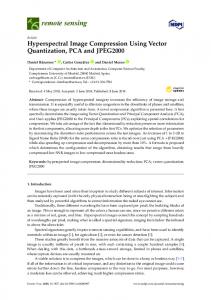
Figure 1
. A full bush of anisotropic wavelet packets with decomposition depth 1 in each direction 2. ANISOTROPIC WAVELET PACKET TRANSFORM
Wavelet transforms can eÆciently be implemented by the application of a pair of quadrature mirror lters. The original data is divided into a low-pass and a high-pass sub-band each of which is down-scaled by 2. In the 2-D case this procedure is applied in horizontal and vertical directions, producing 4 sub-band. If only the double low-pass ltered sub-band is decomposed further recursively, the resulting decomposition is called pyramidal. If all sub-bands can be decomposed, it is called wavelet packet decomposition. The condition that the sub-bands are always either decomposed in both directions or not decomposed at all guarantees that the base functions (wavelets) have the same scale in each direction (isotropic wavelet packets). If this condition is dropped, subbands with anisotropic wavelet packets can be produced which are ltered in only one direction. The fact that in the anisotropic case the method of representing speci c bases by a decomposition tree (including all intermediate sub-bands) is not applicable any more can be explained as follows. Because ltering steps can be interchanged almost arbitrarily, more than one decomposition path can be found for most sub-bands. For instance: Lh Hv and Hv Lh , where Lh denotes horizontal low-pass ltering and Hv vertical high-pass ltering, are two paths that produce the same sub-band. To avoid ambiguous representations of equal bases and redundant calculations, we introduce a graph structure called bush that is a generalisation of trees. Figure Figure 1 shows an example of a bush of anisotropic wavelet packets. The basic idea of bushes is to include all possible decomposition paths for each leaf sub-bands (nondecomposed sub-band) in the bush structure. In this way, a bush serves as a unique representation of an anisotropic wavelet packet basis. According to trees, some operations have to be de ned:
�
child(S; d; k) returns the sub-band that results from low-pass ltering (k = 0) or high-pass ltering (k = 1) of sub-band S in horizontal (d = 0) or vertical (d = 1) dimension.
�
parent(S; d) returns the sub-band T with child(T ; d; k) = S for some k 2 f0; 1g. 3. ANISOTROPIC BEST BASIS
Several methods can be used to nd the best wavelet packet basis for a given purpose. Cost functions can be used that determine a measure of (negative) usability for a given data sequence with respect to a given purpose (cost : L (Z) ! R). The well-known best-basis algorithm for wavelet packet bases is an eÆcient way to calculate the best basis, i.e. the basis that minimises the overall cost function value in the case of additive cost functions. However, this algorithm relies on a tree-like decomposition structure. Therefore, it has to be modi ed to work with bushes. In the isotropic case the algorithm has to decide for each sub-band whether to decompose it or not. In the anisotropic case it can either decompose it horizontally, vertically, both or not at all. To be able to decide this, the best basis of the horizontally and vertically decomposed sub-bands and the minimised cost function values have to be compared against the sub-band's own cost function value. These values have to be determined recursively. The smallest has to be chosen. 13{15
2
1418
Proc. of SPIE Vol. 5150
13
BestDecomp (S ) := if bestdim(S ) > 0 Filter (S; bestdim(S )) BestDecomp (child(S; bestdim(S ); 1)) BestDecomp (child(S; bestdim(S ); 2)) Figure 2.
Best basis decomposition algorithm based on a spanning tree walk. Leaf-vertices are indicated by bestdim(S)=0
Figure 3
. All sub-bands of a full anisotropic wavelet packet decomposition
In the isotropic case it is possible to include the actual calculation of the transform according to the best basis into the determination of the best basis. This avoids a second decomposition run and, thus, saves computation time. However, this is very complicated in the anisotropic case and requires an enormous amount of memory. Additionally, it does not pay because the actual decomposition has a lower complexity than the best basis determination (see below). Therefore, the conventional second-run approach is chosen here.
�
First, we have to calculate the cost for each sub-band. This is done by generating all sub-bands as in Figure 3 and calculating the cost for each sub-band immediately after it is created.
�
Then, we determine for each sub-band the best cost and the best decomposition dimension by:
8 >:bestcost(child( bestcost(child( S
bestcost(S; k) :=
1)) + S; k; 2)) bestdim(S ) := argmin bestcost(S; k)
k
=0
k
= 1:::n
S; k;
k =0:::n
bestcost(S ) := bestcost(S; bestdim(S )) This is a recursive procedure ending at leaf sub-bands (sub-bands at maximum decomposition level) where bestdim(S ) is set to 0 and bestcost(S ) = bestcost(S; 0) = cost(S ).
�
The best basis decomposition is then performed based on original data by applying a tree-walk on a spanning tree. This leads to the algorithm in Figure 2.
As opposed to isotropic wavelet packets, performing a full decomposition and calculating all possible subbands is not the same task for anisotropic wavelet packets. This is, by the way, a consequence of the fact that bushes are not cycle free. To perform a full decomposition, i.e. calculating all sub-bands with maximum decomposition level in each direction, is just as much work as for isotropic wavelet packets, i.e. O(n log n). This is because the resulting sub-bands actually contain isotropic wavelet packets. Accordingly, the decomposition to a speci c basis as in Figure 2 has the same complexity. Proc. of SPIE Vol. 5150
1419
To see how much work it is to calculate all possible sub-bands, look at Figure 3. Again, each coeÆcient is calculated by the inner product of a lter and another sub-band. So we have to count the number of coeÆcients. Following the construction of Figure 3 we get complexity = n((l + 1)d
1) = O(n(log n)d )
where n is thepdata size, d is the dimension (d = 2 in our case) and l is the decomposition depth. It is assumed that l = log d n c. This means that the decomposition depth is increased by 1 if the data size is increased by a factor of 2 in each dimension. 2
4. ZEROTREE CODING
Zero-tree based algorithms arrange the coeÆcients of a wavelet transform in a tree-like manner. All coeÆcients are connected by trees that are rooted in the approximation sub-band's coeÆcients (the sub-band that is lowpass ltered only). Furthermore, a zero-tree is a sub-tree which entirely consists of insigni cant coeÆcients. The signi cance of a coeÆcient is determined by a threshold which plays an imported role in zero-tree coding algorithms. Zero-trees can be viewed as a collection of small coeÆcients with approximately equal spatial position. The SMAWZ codec is used throughout this paper. It is very similar to SPIHT. CoeÆcients are encoded bit-plane-wise. Insigni cant coeÆcients can mostly be grouped in two types of zero-trees, allowing either the root or its direct o�spring to be signi cant, i.e. greater than the bit-plane's threshold. The di�erence between SMAWZ and SPIHT is that SMAWZ applies a spatially oriented coeÆcient scan order and has a xed memory demand because it dispenses with list structures to store the signi cance state and uses bit-maps (signi cance maps) instead. SMAWZ uses arithmetic coding to compress the encoded signi cance, sign and re nement information further losslessly. Context models are basically taken from EBCOT. As with SPIHT, the resulting bit-stream is ratescalable. SMAWZ also is compatible with wavelet packet decompositions. In this case it is much more complicated to build trees of coeÆcients. Similar sub-bands have to be associated to de ne parent-child relationships between their coeÆcients. To do so, sub-bands are connected by trees which we will call similarity trees. Similarity trees are rooted in the approximation sub-band and connect all leaf sub-bands, i.e. all sub-bands that are not decomposed and have to be encoded. The greater the distance from the root sub-band with respect to the similarity tree, the higher should the frequency range of the sub-bands be. This is because the absolute value of the sub-band's coeÆcients should decrease with this distance. To build similarity trees for anisotropic wavelet packets is even more complicated than for isotropic wavelet packets. First of all, it should be clear, which result is expected. Since isotropic bases are a subset of anisotropic bases, the rules for anisotropic decompositions should produce the same similarity trees as the isotropic for isotropic decompositions. For true anisotropic decompositions, the result should closely resemble what one would expect for a similar isotropic decomposition. This is done by dividing the rules for isotropic decompositions into several sub-steps which follow branches in the decomposition bush only in a single dimension. Figure 4 shows these rules. First, the initialisation is simply a connection of the root node to itself. The rules are supposed to substitute the rules for the isotropic case when applied in groups of appropriate order. For instance, the rst rule followed by the second (in the leftmost column) applied to the initial state produces the initial state of the isotropic case. However, if the application of one of these rules is not possible because the anisotropic decomposition bush is not complete (not isotropic), only an approximation of the isotropic case can be achieved. For instance, the second rule of the rightmost column might be chosen instead of the rst. Note that often more than one rule could be applied. In these cases the rst tting rule should be chosen from the list. As soon as similarity trees are de ned, one can easily construct coeÆcient trees. Thus, the SMAWZ algorithm can be applied without major modi cations. 4
16
4
4
1420
Proc. of SPIE Vol. 5150
Initialisation
. Construction of similarity trees for bushes of anisotropic wavelet packets
Figure 4
5. CODING OF THE ANISOTROPIC DECOMPOSITION STRUCTURE
The decoder can decode bit-streams created by encoders described above only if it is capable of constructing decomposition trees and similarity trees exactly as used by the encoder. The similarity trees are constructed from the decomposition structure which should be known by the decoder. However, the decomposition structure has to be encoded to be available to the decoder. For pyramidal wavelet decompositions it is suÆcient for the decoder to know the decomposition depth. This value can either be set to a xed number or encoded into the bit-stream. However, the decomposition structure of wavelet packets is more complicated and can consume a serious amount of bit-rate when it is encoded. Therefore, the encoding has to be eÆcient. Moreover, it is important to have an encoding scheme that is especially eÆcient on more regular decomposition structures. In the isotropic case one bit has to be encoded for each node, indicating whether the decomposition tree branches at this node. If the maximum decomposition depth is known, bits at this level are always zero and can be omitted. Arithmetic coding can be used to further compress this information by grouping the bits of four neighbouring nodes to a single symbol. Again, the anisotropic case is more complicated. To encode a decomposition structure optimally (with a minimum number of bits), it is essential to start with a unique representation of this structure. Otherwise, the encoded bits necessarily contain redundancy. Fortunately, a bush is a unique representation of the decomposition structure. However, this does not mean that it is trivial to encode this structure without redundancy. The algorithm in Figure 5 does this. It takes into account that branches of a node imply certain branches of descendant nodes: Firstly, if the bush branches at a node in dimension d, then all child nodes in any dimension di�erent from d have to branch in dimension d. Secondly, if the bush does not branch at a node in dimension d, then at least one child node in a dimension di�erent from d does not branch in dimension d. The algorithm, therefore, keeps track of dimensions in which nodes must or must not branch (\dobranch" and \nobranch") and does not encode this information. This removes all redundancy from the bush's structure. Additionally, nothing has to be encoded if the maximum decomposition depth is reached (if it is known). At one point, two Boolean values are encoded together where only three states are possible. To encode this without redundancy, an arithmetic coder is necessary. This coder also exploits probabilistic redundancies in the structure. Figure 6 shows the coding results compared to the isotropic case. Note that in both cases regular structures such as the pyramidal and the complete decomposition can be encoded very eÆciently. Higher bit-rates for the anisotropic case are a consequence of the fact that the number of possible bushes is much higher than the number of trees with the same maximum depth.
Proc. of SPIE Vol. 5150
1421
Encode (B ) := Encode (root (B ), ;, ;) Encode (S , dobranch, nobranch) := for all dimensions d if not nobranch[d] and not dobranch[d] Encode (haschildren(d)) if a dimension d exists with haschildren(S; d) for all dimensions e D ; [e] haschildren(S; e) ^ d 6= e for all dimensions e with : haschildren(S; e) D [e] haschildren(child(S; d; 1); e) D [e] haschildren(child(S; d; 2); e) Encode D [e] and D [e] together (note: at least one is false) N [e] :D [e]; N [e] :D [e] Encode (child(S; d; 1), D , N ) Encode (child(S; d; 2), D , N ) 1 2
1
2
1
1
2
1
2
2
1
1
2
2
. Algorithm to encode an anisotropic wavelet packet decomposition structure without redundancy
Figure 5
random pyramidal complete
random pyramidal complete
100000 number of bits
number of bits
100000 10000 1000 100 10
10000 1000 100 10
2
3 4 5 6 7 8 9 maximum decomposition depth
(a) isotropic WP
10
2
3 4 5 6 7 8 9 maximum decomposition depth
10
(b) anisotropic WP
Number of bits necessary to encode a 2-D isotropic wavelet packet tree structure (a) and a 2-D anisotropic wavelet packet bush structure (b). The numbers for the random decomposition represent the maximum of ten randomly generated decompositions Figure 6.
1422
Proc. of SPIE Vol. 5150
6. EXPERIMENTAL RESULTS
A selection of grey-scale images with 512�512 pixel and 8 bit per pixel is used for experiments. The type of images ranges from natural images to arti cial textures. The compression performance of SMAWZ using the pyramidal wavelet transform as well as the conventional and the anisotropic wavelet packet transform is compared. In both wavelet packet transforms the best-basis algorithm is used to determine the basis for decomposition. Three common cost-functions are used in the best-basis algorithm and the results are compared: P Entropy information cost cost(c) = P i ci log ci , Logarithmic energy cost(c) = Pi log ci , 1-norm cost(c) = i jci j where c denotes a set (c ; c ; c ; : : :) of coeÆcients. Figures 7-12 show the coding results for several representative images. The decomposition structures shown are computed with the isotropic an anisotropic best-basis algorithm using the 1-norm as cost function which usually gives the best compression results. Sub- gures (d)-(f) show the compression performance for all three cost functions. Figure 7 shows a well-known image without special features like repeating patterns. While it is known that the compression behaviour of such an image can hardly be improved by the use of conventional wavelet packets, we see that this is also true for anisotropic wavelet packets, which not a big surprise. Figure 8 shows an image that usually performs better with wavelet packets. However, the textures in this image are not anisotropic. Therefore, anisotropic wavelet packets cannot increase the compression performance. The opposite happens in Figure 9. Because of the perspective, the patterns are more dense in horizontal than in vertical dimension. While isotropic wavelet packets can only gain about 0:2 to 0:4 dB, anisotropic wavelet packets improve the compression by 0:6 to 1 dB in PSNR. Much better candidates for wavelet packet compression are regular or nearly regular textures. The textures in Figures 10 and 11 are taken from the Brodatz texture library. For the image in Figure 10, the gain is about 1 to 1:4 dB in the isotropic and 1:6 to 2:3 dB in the anisotropic case. Figure 11 shows similar results, although the pyramidal basis performs much worse in this case (up to 13dB). Anisotropic wavelet packets can still improve compression performance by up to 1 dB. Interestingly, this gain is achieved only above about 0:2 bpp. This shows that there indeed are cases where the optimal decomposition basis depends on the targeted bit-rate, which somehow limits the use of cost functions for the determination of optimal bases. Finally, Figure 12 shows that the di�erence between the isotropic and anisotropic case can be arbitrarily big. In all these gures we see that the 1-norm and the logarithmic energy cost functions produce nearly equal (and quite optimal) compression results. As was shown several times before, the entropy cost function is far from being optimal. It sometimes even degrades the compression performance with respect to the pyramidal basis. 2
2
2
1
2
3
17
7. CONCLUSIONS
As a generalisation of the wavelet packet transform, the anisotropic wavelet packet transform o�ers improved rate-distortion performance of wavelet based compression schemes for certain types of images at the expense of increased computational complexity. Several problems arise when attempting to make wavelet compression algorithms (especially zero-tree algorithms) work with anisotropic wavelet packets, which include: nding a unique representation of the decomposition structure, developing a best-basis algorithm, encoding the decomposition structure without redundancy, and constructing useful coeÆcient trees. These problems have successfully and eÆciently been solved in this paper. While the computational complexity of the decomposition and encoding for a xed anisotropic wavelet packet base equals that of isotropic wavelet packet bases (i.e. O(n log n)), the complexity of the best-basis algorithm is increased to O(n(log n) ). On the other hand, the compressed image quality can be improved for special images containing regular patterns that have di�erent properties in di�erent dimensions. Compared to isotropic wavelet packets, the gain is up to 0:6 dB for some natural images and up to 1 dB for textures in the experiments conducted for this paper. 2
Proc. of SPIE Vol. 5150
1423
(a) image
(b) isotropic
45
(c) anisotropic
45 anisotropic isotropic pyramidal
45 anisotropic isotropic pyramidal
anisotropic isotropic pyramidal
40
40
40
35
35
35
30
30 0.1
0.2
0.5
1
2
30 0.1
(d) 1-norm
0.2
0.5
1
2
0.1
0.2
(e) log. energy
0.5
1
2
(f) entropy
Coding results for image \Lena". Sub- gures (b) and (c) show the best bases according to the 1-norm. (d), (e) and (f) show the PSNR performance depending on the bit-rate in bits per pixel Figure 7.
(a) image 40
(b) isotropic
anisotropic isotropic pyramidal
40
(c) anisotropic
anisotropic isotropic pyramidal
40
35
35
35
30
30
30
25
25
25
0.1
0.2
0.5
(d) 1-norm
1
2
0.1
0.2
0.5
(e) log. energy
1
2
anisotropic isotropic pyramidal
0.1
0.2
0.5
1
2
(f) entropy
Coding results for image \Barbara". Sub- gures (b) and (c) show the best bases according to the 1-norm. (d), (e) and (f) show the PSNR performance depending on the bit-rate in bits per pixel Figure 8.
1424
Proc. of SPIE Vol. 5150
(a) image
(b) isotropic
40
(c) anisotropic
40 anisotropic isotropic pyramidal
40 anisotropic isotropic pyramidal
anisotropic isotropic pyramidal
35
35
35
30
30
30
25
25
25
20
20 0.1
0.2
0.5
1
2
20 0.1
(d) 1-norm
0.2
0.5
1
2
0.1
0.2
(e) log. energy
0.5
1
2
(f) entropy
Coding results for image \Houses". Sub- gures (b) and (c) show the best bases according to the 1-norm. (d), (e) and (f) show the PSNR performance depending on the bit-rate in bits per pixel Figure 9.
(a) image
(b) isotropic
40
(c) anisotropic
40 anisotropic isotropic pyramidal
40 anisotropic isotropic pyramidal
anisotropic isotropic pyramidal
35
35
35
30
30
30
25
25
25
20
20 0.1
0.2
0.5
(d) 1-norm
1
2
20 0.1
0.2
0.5
(e) log. energy
1
2
0.1
0.2
0.5
1
2
(f) entropy
Coding results for image \D51". Sub- gures (b) and (c) show the best bases according to the 1-norm. (d), (e) and (f) show the PSNR performance depending on the bit-rate in bits per pixel Figure 10.
Proc. of SPIE Vol. 5150
1425
(a) image
(b) isotropic
45
(c) anisotropic
45 anisotropic isotropic pyramidal
45 anisotropic isotropic pyramidal
anisotropic isotropic pyramidal
40
40
40
35
35
35
30
30
30
25
25 0.1
0.2
0.5
1
2
25 0.1
(d) 1-norm
0.2
0.5
1
2
0.1
0.2
(e) log. energy
0.5
1
2
(f) entropy
Coding results for image \D49". Sub- gures (b) and (c) show the best bases according to the 1-norm. (d), (e) and (f) show the PSNR performance depending on the bit-rate in bits per pixel Figure 11.
(a) image
(b) isotropic
50 45
(c) anisotropic
50 anisotropic isotropic pyramidal
45
50 anisotropic isotropic pyramidal
45
40
40
40
35
35
35
30
30
30
25
25
25
0.1
0.2
0.5
(d) 1-norm
1
2
0.1
0.2
0.5
(e) log. energy
1
2
anisotropic isotropic pyramidal
0.1
0.2
0.5
1
2
(f) entropy
Coding results for image \Arti cial". Sub- gures (b) and (c) show the best bases according to the 1-norm. (d), (e) and (f) show the PSNR performance depending on the bit-rate in bits per pixel Figure 12.
1426
Proc. of SPIE Vol. 5150
8. ACKNOWLEDGMENTS
The author was supported by the Austrian Science Fund FWF, project no. P13903. REFERENCES
1. R. Koenen, \Overview of the MPEG-4 standard." ISO/IEC JTC1/SC29/WG11, July 1996. 2. ISO/IEC JPEG committee, \JPEG 2000 image coding system | ISO/IEC 15444-1:2000," Dec. 2000. 3. A. Said and W. A. Pearlman, \A new, fast, and eÆcient image codec based on set partitioning in hierarchical trees," IEEE Transactions on Circuits and Systems for Video Technology 6, pp. 243{249, June 1996. 4. R. Kutil, \A signi cance map based adaptive wavelet zerotree codec (SMAWZ)," in Media Processors 2002, S. Panchanathan, V. Bove, and S. Sudharsanan, eds., SPIE Proceedings 4674, pp. 61{71, Jan. 2002. 5. J. M. Shapiro, \Embedded image coding using zerotrees of wavelet coeÆcients," IEEE Trans. on Signal Process. 41, pp. 3445{3462, Dec. 1993. 6. M. Wickerhauser, \INRIA lectures on wavelet packet algorithms." Lecture notes, INRIA, 1991. 7. J. N. Bradley, C. M. Brislawn, and T. Hopper, \The FBI wavelet/scalar quantization standard for gray-scale ngerprint image compression," in SPIE Proceedings, Visual Information Processing II, 1961, pp. 293{304, (Orlando, FL, USA), Apr. 1993. 8. J. Smith and S.-F. Chang, \Space adaptive wavlet packet image compression," in Proceedings from IS&T/SPIE 1996 Symposium on Electronic Imaging: Science & Technology { Still Image Compression II, R. Stevenson, A. Drukarev, and T. Gardos, eds., 2669, IS&T/SPIE, (San Jose, California), Jan. 1996. 9. Z. Xiong, K. Ramchandran, and M. T. Orchard, \Wavelet packet image coding using space-frequency quantization," IEEE Transactions on Image Processing 7, pp. 892{898, June 1998. 10. F. G. Meyer, A. Z. Averbuch, and J.-O. Stromberg, \Fast adaptive wavelet packet image compression," IEEE Trans. on Image Process. 9, pp. 792{800, May 2000. 11. R. Kutil, \The graph structure of the anisotropic wavelet packet transform," in Proceedings of the 7th international scienti c conference devoted to the 25th anniversary of civil engineering faculty and 50th anniversary of technical university Kosice, pp. 41{47, May 2002. 12. R. Kutil, Wavelet Domain Based Techniques for Video Coding. PhD thesis, Department of Scienti c Computing, University of Salzburg, Austria, July 2002. 13. R. Coifman and M. Wickerhauser, \Entropy based methods for best basis selection," IEEE Transactions on Information Theory 38(2), pp. 719{746, 1992. 14. K. Ramchandran and M. Vetterli, \Best wavelet packet bases in a rate-distortion sense," IEEE Trans. on Image Process. 2(2), pp. 160{175, 1993. 15. N. M. Rajpoot, R. G. Wilson, F. G. Meyer, and R. R. Coifman, \A new basis selection paradigm for wavelet packet image coding," in Proceedings of the IEEE International Conference on Image Processing (ICIP'01), pp. 816{819, (Thessaloniki, Greece), Oct. 2001. 16. D. Taubman, \High performance scalable image compression with EBCOT," IEEE Transactions on Image Processing 9(7), pp. 1158 { 1170, 2000. 17. P. Brodatz, Textures: A Photographic Album for Artists and Designers, Dover Publications, New York, 1966. Pictures downloaded from http://www.ux.his.no/~tranden/brodatz.html (Trygve Randen).
Proc. of SPIE Vol. 5150
1427